
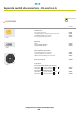
Datasheet
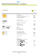


1/L1 3/L2 5/L3
0
2/T1 4/T2 6/T3
13 21
14 22
307307
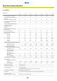
Technical characteristics
Characteristics
20 A 25 A 32 A 50 A 63 A 80 A 100 A
>
Rated insulation voltage Ui (V)
400 400 400 400 400 400 400
>
Conventional free air thermal
c
urrent Ith
Continuous rated current Iu (A)
20 10 10 10 10 10 10
>
Rated operating current Ie (A)
AC 15
230V 6666666
400V - 444444
> Protection against short circuit
by fuse gG (A) 16 10 10 10 10 10 10
>
Max. connection
stranded wire (mm2)
2x2.5 2x2.5 2x2.5 2x2.5 2x2.5 2x2.5 2x2.5
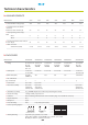
AUXILIARY CONTACTS
>
Characteristics
150
x
100
x
96 220
x
150
x
100 220
x
150
x
100 220
x
150
x
100 220
x
150
x
100 300
x
200
x
100
>
Rating
20, 25
and
32 A 25
and
32 A 50
and
63 A 50
and
63 A 80
and
100 A 80
et
100 A
3P
to
4P 6P
and
6P 3P
to
4P 6P
and
6P 3P
and
3P 4P
to
6P
+NC/NO +NC/NO +NC/NO +NC/NO +NC/NO +NC/NO
20A-6P
>
Cable inputs
2x2Pg16
2 x 2 Pg 21 2 x 2 Pg 21 2 x 2 Pg 29 2 x 2 Pg 29 2 x 2 Pg 21
or 2 x 2 M25
and
2x2P
g29
> Ø
knockouts (mm)
Pg 16: 22.5 28.5 28.5 37.5 37.5 37.5
and
28.5
ISO M25: 25
>
No. o
f knockouts
(t
opandbottom) 2222 2 4
>
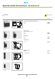
P
anelmount by2screws by4screws
>
Base/cover assembly by 1 screws by 4 screws by 6 screws
self-tapping self-tapping self-tapping
stainless steel stainless steel stainless steel
>
Switch/base assembly on 35 mm DIN rail (this rail is notched for positionning the switch)
>
Handles mounting screwing on shaft pre-pierced cover
>
Insulation Class II installed (provided that the correct insulation plugs are used with the enclosure)
>
Impact withstand IK07
>
Flameproof 650°C
>
Protection rating IP 66 IP 40 (IP 65 upon request)
>
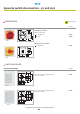
Contact operating diagram
>
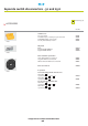
Switch padlocking In general: up to 3 padlocks ø 4 to 8 mm
Switch with 1 auxiliary contact NC/NO: up to 3 padlocks ø 6 to 8 mm
Modular presentation: 1 padlock ø 6 to 8 mm
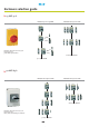
ENCLOSURES
>
1/L1 - 2/T1
3/L2 - 4/T2
5/L3 - 6/T3
13-14
21-22
01
Switch disconnector
Auxiliary
contacts