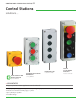
control and signalling units ø 22 Control Stations solutions.... Empty Enclosures Control stations with mushroom heads Standard Control stations with buttons 1, 2, 3, 4 or 5 holes 1, 2 or 3 buttons pre-assembled ÿ ADVANTAGES “All types of control station applications can be achieved” - Multipurpose, pre-equipped with pushbuttons, emergency stops, selector switches, key switches, etc.
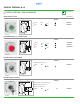
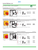
Control Stations ø 22 Technical Info (p. 103) CONTROL STATIONS - NON-ILLUMINATED SPRING RETURN - FLUSH Part Number 47.9 Marking 11 M16/20 Green NO NC 4 LBX10110 1 2 LBX10610 Ø 29.9 Red 3 M16/20 LBX10110 MUSHROOM HEAD Ø 40 - SPRING RETURN 47.9 Marking 22 M16/20 Green NO NC Red Ø 40 Red NO 3 4 LBX107210 1 2 LBX10210 3 4 LBX130028 M16/20 LBX10210 SELECTOR SWITCH - WITH HANDLE 47.9 Marking 23 M16/20 2 Maintained positions - 90° NO 3 LBX12510 4 Ø 29.
Control Stations ø 22 Technical Info (p. 103) CONTROL STATIONS - NON-ILLUMINATED MUSHROOM HEAD Ø 40 - MAINTAINED 47.9 Push-turn to reset Part Number 25.
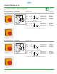
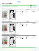
Control Stations ø 22 Technical Info (p. 103) CONTROL STATIONS - NON-ILLUMINATED MUSHROOM HEAD Ø 40 - MAINTAINED 47.9 Key to reset 30.7 Part Number Supplied with 2 keys profile n° 455 Ø 40 M16/20 Red Red Red NC NC + NO 2 NC 1 2 1 2 1 2 3 4 1 2 EMERGENCY STOP EMERGENCY STOP EMERGENCY STOP LBX11210 LBX130071 LBX130072 53.7 For contact blocks attached to operator please contact us. M16/20 LBX11210 MUSHROOM HEAD Ø 40 EN 418 / ISO 13850 47.9 Push-turn to reset 39.
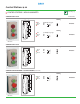
Control Stations ø 22 Technical Info (p. 103) CONTROL STATIONS - NON-ILLUMINATED MUSHROOM HEAD Ø 40 EN 418 / ISO 13850 47.9 Push-pull to reset 39.7 Compliant with the requirements of emergency stop: EN 418 / ISO 13850 Ø 40 M16/20 M16/20 Red Red Red NC NC + NO 2 NC 1 2 1 2 1 2 3 4 1 2 EMERGENCY STOP EMERGENCY STOP EMERGENCY STOP LBX15301 LBX15311 LBX15302 For contact blocks attached to operator please contact us. LBX15101 MUSHROOM HEAD Ø 40 EN 418 / ISO 13850 47.9 Key to reset 40.
Control Stations ø 22 Technical Info (p. 103) CONTROL STATIONS - NON-ILLUMINATED SPRING RETURN - FLUSH 47.9 Marking 11 M16/20 NO NC 3 4 1 2 LBX20120 Ø 29.9 Ø 29.9 Green Red M16/20 LBX20120 SPRING RETURN - FLUSH/MUSHROOM 47.9 Marking Green Red 11 LBX210660 3 4 1 2 Ø 32 Ø 29.9 M16/20 NO NC M16/20 LBX210660 SPRING RETURN/MAINTAINED - FLUSH/MUSHROOM (PUSH-TURN) 47.9 Marking 11 M16/20 NO NC Ø 32 Ø 29.
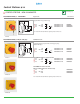
Control Stations ø 22 Technical Info (p. 103) CONTROL STATIONS - NON-ILLUMINATED SPRING RETURN - FLUSH Part Number 47.9 Marking 11 M16/20 24VAC/DC Pilot Light 3 4 NO NC 1 2 Ø 29.9 Ø 29.9 Red Green Red LBX30008 Marking Ø 29.9 Red Green Red 130VAC/DC Pilot Light 3 4 NO NC 1 2 LBX323870 M16/20 LBX323870 SPRING RETURN - FLUSH 47.9 Marking 11 M16/20 NO NC NO 3 4 1 3 2 4 LBX30430 Ø 29.9 Ø 29.9 Ø 29.
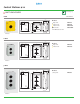
Control Stations ø 22 Technical Info (p. 103) EMPTY ENCLOSURES 1 HOLE Part Number 47.9 42.5 74 M16/20 Ø 4.5 74 59.5 Black base Grey cover Yellow cover Yellow cover* Black cover 8 16.5 LBX0100 LBX0100J LBX0100JB LBX0100NR Ø 4.5 * with ‘Emergency Stop’ text M16/20 LBX0100J 2 HOLES 47.9 42.5 74 M16/20 Ø 4.5 LBX0200 LBX0200J 107 92.5 Black base Grey cover Yellow cover 8 16.5 Ø 4.5 M16/20 LBX0200 3 HOLES 47.9 42.5 74 M16/20 Black base Grey cover 8 16.5 140 125.5 Ø 4.5 Ø 4.
Control Stations ø 22 Technical Info (p. 103) EMPTY ENCLOSURES 4 HOLES Part Number 47.9 16.5 42.5 74 M16/20 Black base 8 Grey cover LBX0400 173 158.5 Ø 4.5 Ø 4.5 M16/20 LBX0400 5 HOLES 47.9 42.5 74 M16/20 Black base Grey cover 8 16.5 LBX0500 206 191.5 Ø 4.5 Ø 4.
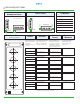
SPECIAL REQUEST FORM Mounting Number of Holes Cable Gland Top circle number of holes 3 4 5 Vertical Left Horizontal Right 2 Vertical 1 Comments Bottom Horizontal Duty Label Marking Blocks Switches Enter contact block part number in each mounting position. LED modules must be in position 3. Enter switch part number for each position. For text or symbol on the switch head enter text or symbol code.
LEGEND PLATES FOR LBX ENCLOSURES INDIVIDUAL LEGEND PLATES Part Number Plastic - Rectangular shape Without Engraving Red Black Yellow White Blue Alu LWB11 LWB13 LWB14 LWB15 LWB16 LWB19 LWB13 With Text (see p. 80 to 83) for Horizontal Mounting Code to be added at the end of the part number. For custom text or symbol please contact us.
Control Stations ø 22 PRE-DRILLED POLYCARBONATE ENCLOSURES Cable Gland BPA202 Dimensions (mm) Number of Holes Hole Entries L W D A B Part Number 1 1 x PG13-GY 82 80 55 70 50 BPA201 2 1 x PG13-GY 120 80 55 108 50 BPA202 3 1 x PG13-GY 160 80 55 148 50 BPA203 1 1 x PG13-GY 82 80 85 70 50 BPP201 2 1 x PG13-GY 120 80 85 108 50 BPP202 3 1 x PG13-GY 160 80 85 148 50 BPP203 W D L L A Ø4.