
User's Manual


®
Due to continuous research, product improvements and enhancements,
Badger Meter reserves the right to change product or system specifications
without notice, except to the extent an outstanding bid obligation exists.
Copyright © Badger Meter, Inc. 2002. All rights reserved.
Please see our website at
www.badgermeter.com
for specific contacts.
BadgerMeter,Inc.
P.O. Box 245036, Milwaukee, WI 53224-9536
(800) 876-3837 / Fax: (888) 371-5982
www.badgermeter.com
TESTING
After connections are complete, test the entire installation including the
RTR, wiring, and remote module for proper operation in accordance
with the instructions supplied with the module.
Install the RTR on the water meter and secure it using the Torx screw
provided.
TROUBLE SHOOTING
An analog ohm meter will show an "open" reading when connected
across the OUTPUT leads of the RTR. When operating the RTR, the
ohm meter should show a momentary deflection toward zero when the
RTR sends a signal.
LICENSE REQUIREMENTS
This device complies with Part 15 of the FCC Rules. Operation of this
device is subject to the following two conditions: (1) This device may
not cause harmful interference, and (2) this device must accept any
interference received, including interference that may cause undes-
ired operation. Any changes made by the user not approved by Badger
Meter can void the user's authority to operate the equipment. No
license is required by the utility to operate a ORION meter reading
system.
If the wire is cut or broken and requires a field splice after
initial installation, connect like colors to maintain proper
installation.
Place the two plastic cable ties on wires and tighten securely for
strain relief. Remove excess cable tie with wire cutting device.
Do not strip any insulation from the ends of the wires before
you push them into the connector.
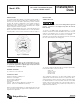
If using a 3M Scotchlok Model
E-9C Cartridge tool, push the
ends of the wires to be
connected into the connector at
the end of the crimping tool, as
shown to the left.
Then squeeze the crimping tool
handle until it pushes the
connector (now crimped) out of
the tool when you release the
handle.
A connector is crimped
properly if the
top of the movable, yellow
center part is flush with the
top of the connector body.
Crimping the connectors
sometimes squeezes some
sealant out of them. The sealant
protects the inside of the
connector against insects,
moisture, and other
contaiminants.
The sealant may cause minimal
eye and skin irritation. Avoid eye
contact. Avoid prolonged or
repeated skin contact.
Push the wires that are to be
connected together as far as
possible into the connector.
Place the connector (with wires)
into the jaws of the crimping tool.
Crimp the connector by
squeezing the handles until the
connector looks like this.
Continue to apply pressure for
three seconds.
Crimping Tool
3M Scotchlok Model E-9C
Cartridge Tool
Recordall
®
, ORION
®
and RTR
®
are registered trademarks of Badger Meter, Inc.
Torx is a registered trademark of Camcar, Division of Textron, Inc. 3M
TM
and
Scotchlok
TM
are trademarks of 3M.