ORION® Water Endpoints Image shown represents ORION Cellular LTE endpoint installed, as per instructions, through non-metal pit lid ORI-UM-00025-EN-FCC (January 2021) Installation Manual
ORION® Water Endpoints CONTENTS SCOPE OF THIS MANUAL . . . . . . . . . . . . . . . . . . . . . . . . . . . . . . . . . . . . . . . . . . . . . . . . . . . . . . . . . . . . . . . . . . . . . . . . . 3 PRODUCT UNPACKING AND INSPECTION . . . . . . . . . . . . . . . . . . . . . . . . . . . . . . . . . . . . . . . . . . . . . . . . . . . . . . . . . . . . . .
Scope of this Manual SCOPE OF THIS MANUAL This manual contains installation instructions for ORION® Cellular endpoints: C, LTE-M, LTE-MS, LTE and the ORION Fixed Network (SE), Migratable (ME) and Classic (CE) water endpoints. ORION endpoints installation must comply with all applicable federal, state and local rules, regulations and codes. Failure to read and follow these instructions can lead to misapplication or misuse of this product, resulting in personal injury and damage to equipment.
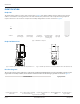
Identification IDENTIFICATION Endpoints The ORION water endpoint is a three-wire metering device (Figure 1) for indoor/outdoor use. Each endpoint has a unique numeric serial number on the tag attached to the cable harness (wire) and etched on the endpoint housing. Endpoints require connection to an encoder to complete the assembly. Badger Meter encoders are shown in Figure 4.
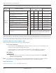
ORION Cellular Endpoints: C, LTE-M, LTE-MS, LTE ORION CELLULAR ENDPOINTS: C, LTE-M, LTE-MS, LTE This section covers configuration, encoder compatibility and installation for ORION Cellular C, LTE-M, LTE-MS and LTE endpoints. The serial number is engraved on one side of the endpoint base, and the FCC label is displayed on the other side. The C, LTE-M and LTE endpoints have yellow FCC labels. The LTE-MS endpoint has a white FCC label. (See Figure 5).
ORION Cellular Endpoints: C, LTE-M, LTE-MS, LTE ORION endpoint wires: Red = Power/Clock; Black = Ground; Green = Data Endpoint Label Endpoint Wire Colors Red Black Green Encoder Connectivity Badger Meter HR-E LCD or HR-E encoders or E-Series Ultrasonic and Ultrasonic Plus Meter with High Resolution output Metron-Farnier Hawkeye* Mueller Systems 420 Solid State Register (SSR) LCD* ORION Cellular C, LTE-M, LTE-MS, LTE Neptune ProRead, E-coder, ARB-V* or ProCoder with encoder output Neptune registers wit
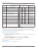
ORION Fixed Network and Migratable Endpoints ORION FIXED NETWORK AND MIGRATABLE ENDPOINTS This section includes configuration, encoder compatibility and installation information for ORION Fixed Network (SE) and ORION Migratable (ME) endpoints. The serial number is engraved on the endpoint body. Serial numbers range from 30000000 to 59999999. Endpoint Configurations The following configuration options are available.
ORION Fixed Network and Migratable Endpoints ORION endpoint wires: Red = Power/Clock; Black = Ground; Green = Data Endpoint Label Encoder Connectivity Red Endpoint Wire Colors Black Green Reading Resolution Badger Meter HR-E LCD or HR-E encoders, or E-Series Ultrasonic Meter with High Res output Red Black Green Up to eight (8) most significant digits ADE or ENC Badger Meter ADE or E-Series Ultrasonic Meter with ADE output Red Black Green Up to six (6) most significant digits RTR Badger Met
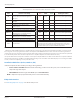
ORION Classic Endpoints ORION CLASSIC ENDPOINTS This section includes configuration, encoder compatibility and installation information for ORION Classic (CE) endpoints. The serial number is engraved on the endpoint body. Serial numbers range from 70000000 to 89999999. Endpoint Configurations The following configuration options are available.
Activating Endpoints ORION endpoint wires: Red = Power/Clock; Black = Ground; Green = Data Endpoint Label Endpoint Wire Colors Red Black Green Encoder Connectivity Reading Resolution Red Black Green Up to seven (7) most significant digits RTR Badger Meter RTR or E-Series Ultrasonic Meter with RTR output Red Black Green Up to seven (7) most significant digits Green Black Red Up to seven (7) most significant digits Red Black Green Up to seven (7) most significant digits Red Black Gre
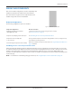
Activating Endpoints ACTIVATING ENDPOINTS Activation is dependent on whether the endpoint is in “Pause” (soft sleep) or “Stop“ (hard sleep) radio mode. The ORION Endpoint Utility software can be used to identify the endpoint radio mode. Smart Activation for Endpoints in Pause Mode All ORION endpoints offer a Smart Activation feature which utilizes consumption to automatically start an endpoint in Pause mode.
Changing Registration for an Existing Endpoint Assembly Confirming Installation - ORION Cellular C, LTE-M, LTE-MS, LTE Before leaving the installation site, the installer can confirm endpoints are active and communicating. 1. BEACON® AMA users can check ORION Cellular endpoint activation status with the ORION Endpoint Status tool. Endpoints do not need to be provisioned in BEACON AMA to display using the tool. See "Endpoint Status Tool for ORION Cellular Endpoints" on page 28 for more information. 2.
Endpoint Installation Kits ENDPOINT INSTALLATION KITS Type For Use With Description Kit Part Number REMOTE All ORION endpoints 64394-032 Wall Cover Install Kit 64394-032 REMOTE 64394-032, 66009-004 67625-001 IR Holder for Wall Cover Install Kit 67625-001 REMOTE ORION Cellular C, LTE-M, LTE-MS, LTE 64394-031 Wall Bracket Install Kit - ORION Cellular LTE 64394-031 REMOTE ORION SE, ME, CE 69406-001 Mounting Bracket Install Kit for ORION Endpoint and E-Series Ultrasonic Meter 69406-001 REMO
64394-032 Wall Cover Install Kit 64394-032 WALL COVER INSTALL KIT Wall Cover Install Kit (64394-032) is recommended for proper mounting of an endpoint for indoor and outdoor remote applications, and is designed to provide an environmentally protected area for gel splice connections (if needed). Outside dimensions are shown in Figure 9. For use with: All ORION endpoints 4.70 in. (119 mm) 5.80 in. (147 mm) .25 in. (6 mm) 2.82 in.
64394-032 Wall Cover Install Kit • If the endpoint has an in-line connector, place the connector inside with the endpoint and route the connector cable through the cutout on the bottom. NOTE: If used, place gel splice connections inside the enclosure. NOTE: See "Outdoor Installation for Endpoint with In-line Connector" on page 16 for additional information about installing the endpoint outdoors with the wall cover enclosure. 5.
64394-031 Wall Bracket Install Kit - ORION Cellular LTE Outdoor Installation for Endpoint with In-line Connector Figure 15: Outdoor endpoint installation Meter-side connector harnesses are available with Twist Tight and Nicor connectors in the following lengths.
69406-001 Mounting Bracket Install Kit for ORION Endpoint and E-Series Ultrasonic Meter 69406-001 MOUNTING BRACKET INSTALL KIT FOR ORION ENDPOINT AND E-SERIES ULTRASONIC METER Mounting Bracket Install Kit (69406-001) is designed to securely install an ORION endpoint to an E-Series Ultrasonic meter for non-submerged indoor and outdoor remote applications. The bracket can be used for installations in any nonmetallic joist, wall or pit application. For use with: ORION SE, ME and CE endpoints 2.35 in. 60 mm .
69406-001 Mounting Bracket Install Kit for ORION Endpoint and E-Series Ultrasonic Meter 64394-029 WALL BRACKET INSTALL KIT Wall Bracket Install Kit (64394-029) can be used to securely install an ORION endpoint. For non-submerged indoor and outdoor applications, the bracket can be used in any indoor or outdoor nonmetallic joist, wall or pit application. For use with: All ORION endpoints except ORION Cellular C, LTE-M, LTE-MS, LTE endpoints You will need the following items.
64394-008 C-Clamp Wall Bracket Install Kit Mount the endpoint assembly 7. Make sure the endpoint antenna is upright (Figure 28) when you place it into its final position. 8. Using two customer-supplied screws, secure the bracket assembly using the pilot holes you drilled in Step 1. Installation is complete. Figure 28: Endpoint positioning 64394-008 C-CLAMP WALL BRACKET INSTALL KIT C-Clamp Wall Bracket Install Kit (64394-008) can be used when mounting an endpoint to a wall.
64394-003 Pipe Install Kit 64394-003 PIPE INSTALL KIT Pipe Install Kit (64394-003) with mounting support bracket (Figure 30) is designed for pipe installations on a 3/8, 5/8 and 1/2 inch rebar or 1/2 inch schedule 40 PVC pipe. For use with: All ORION endpoints. For ORION Cellular endpoints, the kit can be used for indoor and remote installations, but should NOT be used under a pit lid. 1/2 in. Rebar 5/8 in. Rebar Hex head bolt can be used in any slot, as needed 3/8 in. Rebar 1/2 in.
64394-023 Commercial Meter Mounting Bracket Install Kit 64394-023 COMMERCIAL METER MOUNTING BRACKET INSTALL KIT Commercial Meter Mounting Bracket Install Kit (64394-023) is designed for use with most Badger Meter Turbo, Compound Series and Fire Service Disc bypass meter lines. Use the kit to securely mount an ORION endpoint to a meter. For use with: All ORION endpoints You will need a torque wrench set for installation.
64394-030 Thru-the-Lid Install Kit Meter Ft-lb Meter Ft-lb 2-inch Turbo Series Meter 10.9 2-inch Compound Series Meter 16.7 3-inch Turbo Series Meter 37.5 3-inch Compound Series Meter 33.3 4-inch Turbo Series Meter 37.5 4-inch Compound Series Meter 33.3 6-inch Turbo Series Meter 37.5 6-inch Compound Series Meter 33.3 Heavy Duty Bypass M70 21.0 Heavy Duty Bypass M170 50.0 Installation is complete. Turn the water back on.
64394-009 Integrated Pit Lid Hanger Install Kit 64394-009 INTEGRATED PIT LID HANGER INSTALL KIT Integrated Pit Lid Hanger Install Kit (64394-009) is designed for ORION endpoints installed below composite and plastic lids that have an integrated AMR/AMI endpoint hanger. For use with: ORION Fixed Network, Migratable, and Classic endpoints To install an ORION endpoint with this kit, follow these steps and refer to Figure 41. 1. Thread the lock nut onto the top of the ORION endpoint as shown. 2.
Integral Endpoint Installation INTEGRAL ENDPOINT INSTALLATION ORION SE, ME and CE endpoints are available in an integral configuration in which the endpoint and encoder are connected in one assembly. There are two types of integral configurations. This section includes instructions for mounting an integral endpoint on a meter and also provides instructions for disassembling both types of integrals.
Integral Endpoint Installation Removing the Endpoint from the Assembly Housing NOTE: The endpoint cover connects to the base with three tabs: one in the back and two in the front (closest to the encoder.) 1. Remove the integral assembly from the meter. • • Remove the security screw at the base of the assembly. Keep the screw for remounting the encoder assembly. Turn the assembly (as one piece) 1/4 turn, counter-clockwise and lift the assembly off the meter. 2.
Integral Endpoint Installation HR-E Encoder Integral Configuration 6.7 in 170 mm 4.21 in. 107 mm Figure 48: HR-E Integral assembly with additional wire Figure 49: HR-E Integral base dimensions Configuration The ORION HR-E Integral Assembly is shown in Figure 48. The endpoint has a 3-foot length of wire stored inside the bottom of the assembly housing. The endpoint can be removed from the housing, if necessary, and mounted away from the encoder.
Integral Endpoint Installation 2. Remove the endpoint wire under the breakaway plate. • Turn the endpoint/encoder assembly over. • Grasp the pull tab located to the right of the encoder seal screw with pliers (Figure 51). Then pull and remove the bottom breakaway plate from the housing to expose the wire. The plate is scored to facilitate removal. • With your fingers, remove the three feet of endpoint wire from the housing. NOTE: The wire is attached to the endpoint.
Endpoint Status Tool for ORION Cellular Endpoints ENDPOINT STATUS TOOL FOR ORION CELLULAR ENDPOINTS BEACON® AMA users can check the activation status of ORION Cellular endpoints with the ORION Endpoint Status tool. Several minutes after installation, the tool displays ORION Cellular endpoints assigned to you. Endpoints do not need to be provisioned in BEACON AMA to display. The browser-based tool can be viewed on a computer or mobile device. An Internet connection is required.
Endpoint Status Tool for ORION Cellular Endpoints 5. Select an endpoint in the list to see the endpoint raw read. A window opens, like the examples shown in Figure 56. NOTE: Information in the first three fields is captured at the time of activation. Information in the next three fields is current information.
In-line Connectors IN-LINE CONNECTORS In-line connectors are used to allow AMA/AMR/AMI device connectivity without the need for a field splice kit. There are three available in-line connector types: Twist Tight, 308, Nicor. When ordered separately, the endpoint and encoder (or electronic meter) in-line connectors come with removable caps, which can be removed in the field before joining the connector ends. With the proper orientation, the connector ends go together easily. No tools are necessary.
Using Gel Caps to Connect an Encoder 308 Connector To use the 308 connector, follow these steps and refer to Figure 60. 1. Squeeze the notched area and pull to remove the cap(s). 2. Align the notches inside each connector and push the ends together. You will hear a “click“ when the connector ends are firmly seated and secure.
Using Gel Caps to Connect an Encoder USING GEL CAPS TO CONNECT AN ENCODER For those connections that are not factory wired or equipped with in-line connectors, follow these guidelines for using gel caps when splicing is required, either for installation or to fix a connection after a tamper. Refer to the wiring charts for each ORION endpoint, starting on page 6. NOTE: • For pit environments, splice connections require a field splice kit (62084-001), which can be ordered separately.
Using Gel Caps to Connect an Encoder • Using a crimping tool such as the Badger Meter Parallel Pliers (59983-001), place the gel cap with the wires into the jaws of the crimping tool. Figure 64: Gel cap in crimping tool • Crimp the gel cap by squeezing the crimping tool handles until the gel cap is completely compressed. The Badger Meter Parallel Pliers is designed to apply just enough pressure to crimp the gel cap. Apply pressure for three seconds.
ORION® Water Endpoints INTENTIONAL BLANK PAGE Page 34 ORI-UM-00025-EN-FCC January 2021
Installation Manual INTENTIONAL BLANK PAGE January 2021 ORI-UM-00025-EN-FCC Page 35
ORION® Water Endpoints SMART WATER IS B ADGER ME T ER ADE, BEACON, M-Series, ORION and RTR are registered trademarks of Badger Meter, Inc. Other trademarks appearing in this document are the property of their respective entities. Due to continuous research, product improvements and enhancements, Badger Meter reserves the right to change product or system specifications without notice, except to the extent an outstanding contractual obligation exists. © 2021 Badger Meter, Inc. All rights reserved. www.