Turbine Flow Meter FloClean Sanitary Turbine Flow Meter TUR-UM-00288-EN-01 (November 2013) User Manual
Turbine Flow Meter, FloClean Sanitary Flow Meter Page ii November 2013
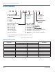
User Manual CONTENTS INTRODUCTION . . . . . . . . . . . . . . . . . . . . . . . . . . . . . . . . . . . . . . . . . . . . . . . . . . . . . . . . . . . . . . . . . . . . . . .5 THEORY OF OPERATION . . . . . . . . . . . . . . . . . . . . . . . . . . . . . . . . . . . . . . . . . . . . . . . . . . . . . . . . . . . . . . . . . .5 SPECIFICATIONS . . . . . . . . . .
Turbine Flow Meter, FloClean Sanitary Flow Meter Page iv November 2013
User Manual INTRODUCTION The Blancett FloClean turbine flow meter is designed with wear resistant moving parts to provide trouble-free operation and long service life. The durable 316L stainless steel construction provides a cost efficient flow measurement system that offers excellent accuracy and repeatability. The FloClean turbine meter repair kit is designed for easy field service of a damaged flow meter, rather than replacing the entire flow meter. See Repair Kits on page 12 for information.
Turbine Flow Meter, FloClean Sanitary Flow Meter MODEL NUMBERS B 16 C - X X Bearing Material A - Ni Bindery Tungsten Carbide Sanitary Rating C - COP/SOP (3A Compliant) Ferrule Size 0 - 0.984 in. 1 - 1.984 in. 2 - 3.047 in. 2 X X Calibration A - 5 Point (std) B - 10 Point C - 20 Point Meter Body Hub A - With Hub ¹ B - No Hub Pickup Option 0 - NEMA 6 - Magnetic 1 - NEMA 6 - Mag 2 - Non NEMA 6 - Magnetic ² 3 - Non NEMA 6 - Mag ² 4 - Non NEMA 6 - Active 4...
User Manual INSTALLATION THE METER SHOULD NOT BE SUBJECTED TO TEMPERATURES ABOVE 300° F (149° C), OR BELOW –150° F (–101° C) OR THE FREEZING POINT OF THE METERED LIQUID. HIGH TEMPERATURES WILL DAMAGE THE MAGNETIC PICKUP, WHILE LOWER TEMPERATURES WILL LIMIT THE ROTATION OF THE ROTOR. INCOMPATIBLE FLUIDS COULD DETERIORATE INTERNAL PARTS AND CAUSE THE METER TO READ INACCURATELY.
Turbine Flow Meter, FloClean Sanitary Flow Meter Display 1 Isolation Valve 2 FloClean Turbine Flow Meter Isolation Valve 10 Pipe Diameters Minimum 5 Pipe Diameters Minimum Bypass Line Figure 3: Installation with bypass line This is true with any restriction in the flow line that may cause the liquid to flash. If necessary, air eliminators should be installed to ensure that the meter is not incorrectly measuring entrained air or gas.
User Manual Wiring Typical wiring configurations for the available pickup options are shown in Figure 5, Figure 6, and Figure 7.
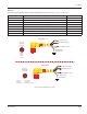
Turbine Flow Meter, FloClean Sanitary Flow Meter Standard Mag Pickup (Socket End) Pickup Option 2 & 6 B - Yellow (-) = Signal B A A - Blue (+) = Signal Pins A = Signal B = Signal Amplified Mag Pickup (Socket End) C Pickup Option 3 A - Red = Power (5…30V DC) B - Black = Common C - Green = Output Pulse or (0…10V DC) Clear A B Pins A = Power B = Common C = Output Signal Figure 6: Wiring for non-NEMA 6 magnetic pickups Active Sensor 4...20 mA (Socket End) Pickup Option 4 3 4 2 5 1 1 - Red = +4.
User Manual Operational Startup The following steps should be followed when installing and starting the meter. MAKE SURE THAT FLUID FLOW HAS BEEN SHUT OFF AND PRESSURE IN THE LINE RELEASED BEFORE ATTEMPTING TO INSTALL THE METER IN AN EXISTING SYSTEM. 1. After meter installation, close the isolation valves and open the bypass valve. Flow liquid through the bypass valve for sufficient time to eliminate any air or gas in the flow line. 2.
Turbine Flow Meter, FloClean Sanitary Flow Meter Rotor Assembly Magnetic Pickup Jam Nut Sleeve Bearing Meter Body Rotor Support Thrust Ball (Removable) Retaining Ring Stnd. #28-04 Auth. #956 Manufacturer’s Label and 3-A Symbol B16C 3-A Series (COP/SOP) FloClean Meters Figure 9: FloClean cross sections METER REPAIR AND CLEANING Repair Kits Each FloClean repair kit is factory calibrated to ensure accuracy throughout the entire flow range.
User Manual Service Procedures HIGH-PRESSURE LEAKS ARE DANGEROUS AND CAUSE PERSONAL INJURY. MAKE SURE THAT FLUID FLOW HAS BEEN SHUT OFF AND PRESSURE IN THE LINE RELEASED BEFORE ATTEMPTING TO REMOVE THE METER. 3-A Turbine Disassembly and Cleaning Procedure NNOTE: Refer to Figure 10 for relative positions of repair kit components. 1. Remove the magnetic pickup from the meter body to avoid damage during procedure. 2. Remove the retaining ring from one end of the meter. 3.
Page 14 A A Remove Rotor Stnd. #28-04 Auth.
User Manual B16C SERIES (COP/SOP) – 3-A TURBINE INSTALLATION NNOTE: This procedure applies to installation of replacement turbine repair kits and re-installation of cleaned or sanitized turbine. IIMPORTAN Before reassembly, note there are weep holes on each rotor support. These weep holes must be facing down toward the bottom of the meter body when installed. The meter must be reassembled with the arrowheads on the rotor pointed in the direction of fluid flow.
Turbine Flow Meter, FloClean Sanitary Flow Meter TROUBLESHOOTING GUIDE Trouble Possible Cause Remedy Meter indicates higher than actual flow rate • Cavitation • Debris on rotor support • Build up of foreign material on meter bore • Gas in liquid • • • • Increase back pressure Clean meter Clean meter Install gas eliminator ahead of meter Meter indicates lower than actual flow rate • Debris on rotor • Worn bearing • Viscosity higher than calibrated • Clean meter and add filter • Install new repai
User Manual 3-A CERTIFICATE Initially Issued: 3/19/1998 Authorization No.: 956 This Is To Certify That Blancett Division of Racine Federated, Inc. 8635 Washington Avenue, Racine, WI 53406 Is hereby authorized to continue to apply the 3-A Symbol to the models of equipment, conforming to 3-A Sanitary Standards for: Flow Meters, Number: 28-04, set forth below: B16C-003A-xxx, B16C-005A-xxx, B16C-007A-xxx, B16C-105A-xxx, B16C-107A-xxx, B16C-108A-xxx, B16C-110A-xxx, B16C-115A-xxx, B16C-220A-xxx.
Turbine Flow Meter, FloClean Sanitary Flow Meter INTENTIONAL BLANK PAGE Page 18 November 2013
User Manual INTENTIONAL BLANK PAGE November 2013 Page 19
Blancett is a registered trademark of Badger Meter, Inc. Other trademarks appearing in this document are the property of their respective entities. Due to continuous research, product improvements and enhancements, Badger Meter reserves the right to change product or system specifications without notice, except to the extent an outstanding contractual obligation exists. © 2013 Badger Meter, Inc. All rights reserved. www.badgermeter.