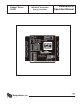
Badger® Series 340N2 METASYS® Compatible Energy Transmitter Installation & Operation Manual 872033 BadgerMeter, Inc. Rev.
Introduction The Badger Meter Series 340N2 Btu transmitter is an economical, compact device for sub-metering applications using Johnson Controls Metasys® Network Companion™ and Facilitator™ Supervisory Systems. The Badger® Series 340N2 works in conjunction with a flow sensor and two temperature sensors to calculate thermal energy by measuring liquid flow and inlet and outlet temperatures in a closed pipe system. The Series 340N2 requires two 10 kW thermistors for temperature input.
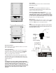
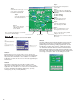
Sensor Wiring All flow sensor types connect to the four terminal header labeled “Sensor Input”. Series 200 Connect the red wire to Series 340N2 Sensor signal (+), connect the flow sensor black wire to Series 340N2 Sensor signal (-) and the bare wire to shield. SDI Series (standard pulse output option) Connect SDI number 3 sensor signal to the Series 340N2 transmitter sensor signal (+) and the SDI number 2 sensor common terminal to Series 340N2 transmitter sensor signal (-).
Temp 2 Mat Temp 1 10KΩ Thermistors Sample Sensor Wiring Diagram Thermistor Wiring Diagram Temperature Element Wiring The Badger Meter thermistors are not polarity sensitive. Connect the thermistor closest to the flow sensor to the Series 340N2 terminal block marked Temp 1 number 3 and number 2. The other thermistor wires to Series 340N2 terminal marked Temp 2 number 3 and number 2.
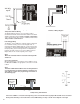
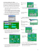
Programming the Badger® Series 340N2 Prior to introducing the Badger Series 340N2 onto a N2 network, it needs to be configured for the pipe’s size, desired units of measure, and its the default network address should be changed to an unused address to avoid any conflicts with other instruments on the N2 network. Programming the Series 340N2 is accomplished using the Badger Meter PC software. 1. 2. 3. 4.
Step 2 Select the desired temperature sensor units.
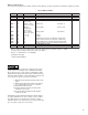
Metasys® Network Setup To incorporate point data into the Metasys Network and the Metasys Companion Network the following Point Map is provided Series 340N2 Point Map 340N2 Point Map 1 2 NPA UNITS BO 01 n/a ADF 01 ADF 02 ADF 03 ADF 04 ADF ADF ADF ADF ADF ADF 05 06 07 08 09 0A gpm * (flow rate conv coeff) gallons * (flow total conv coeff) kBtu/hr * (energy rate conv coeff) Btu * (energy total conv coeff) °F or °C °F or °C n/a n/a n/a n/a ADI 01 n/a NPT POINT DESCRIPTION binary output
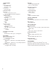
SPECIFICATIONS Power Power supply options: 12-35 VDC +/- 5% 12-24 VAC +/- 10% Current Draw: 60 mA @ 12 VDC N2 Output RS-485 output compliant with EIA / TIA - 485 standards Flow Sensor Input All sensors: Excitation voltage 3 wire sensors: 7.9 – 11.4 VDC 270W source impedance Pulse type sensors: Signal amplitude: 2.
FACTORY DEFAULTS Serial Number Version Temperature Units Sensor Type K= Offset= Flow Rate Units Flow Total Units Energy Rate Units Energy Total Units Energy Calculation Flow Filter Energy Filter Scaled Pulse Output Units Scaled Pulse Output Units Per Pulse Scaled Pulse Output Pulse Width Default Values n/a n/a °F Pulse 1 0 gpm gallons kBtu/hr Btu absolute 0 0 energy 1 100 Customer Values 9
(This page intentionally left blank.
(This page intentionally left blank.) Badger® and Data Industrial® are registered trademarks of Badger Meter, Inc. Metasys® is a registered trademark of Johnson Controls. Windows® is a registered trademark of Microsoft Corporation. Due to continuous research, product improvements and enhancements, Badger Meter reserves the right to change product or system specifications without notice, except to the extent an outstanding contractual obligation exists. Please see our website at www.badgermeter.