
Owner's manual


2
INTRODUCTION
The Badger Meter Series 340N2 Btu transmitter is an
economical, compact device for sub-metering applications
using Johnson Controls Metasys
®
Network Companion™ and
Facilitator™ Supervisory Systems.
The Badger
®
Series 340N2 works in conjunction with a
ow sensor and two temperature sensors to calculate
thermal energy by measuring liquid ow and inlet and outlet
temperatures in a closed pipe system. The Series 340N2
requires two 10 kW thermistors for temperature input. The ow
input may be provided by any Badger Meter sensor and many
other pulse or sine wave signal ow sensors.
The onboard microcontroller and digital circuitry make precise
measurements and produce accurate, drift-free outputs. The
Series 340N2 is congured using Badger Meter Windows
®
based programming software. Calibration information for the
ow sensor, units of measurement and output scaling may be
preselected or entered in the eld. Btu transmitter information
is available when connected to a PC or laptop computer. This
information includes real-time ow rate, ow total, both T1 and
T2 temperature probe information, energy rate, and energy
total.
The Series 340N2 transmitter features two LED’s to verify input
and output signals.
The primary output for the Series 340N2 is an isolated solid
state switch closure that is user programmed for units of energy
or ow. The output pulse width is adjustable from 50 mS to 5
sec.
The secondary output is the Johnson Controls N2
communications protocol that allows the Series 340N2 to be
assigned an address and allow all measurement parameters:
inlet and outlet temperature, ow rate, ow total, energy rate
and energy total to be transmitted from as many as 255 units on
a single 3-wire RS-485 bus.
The Series 340N2 Btu transmitter operates on AC or DC power
supplies ranging from 12 to 24 volts.
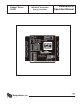
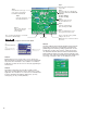
The compact cast epoxy body measures 3.65”(93mm) x
2.95”(75mm) and can be easily mounted in panels, enclosures
or on DIN rails.
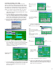
Series 340N2 Dimensions
INSTALLATION
Mechanical Installation
The series 340N2 transmitter may be surface mounted onto a
panel, attached to DIN rails using adapter clips or wall mounted
using optional enclosures.
Location
Although the Series 340N2 device is encapsulated, all wiring
connections are made to exposed terminals. The unit should
be protected from weather and moisture in accordance with
electrical codes and standard trade practices.
In any mounting arrangement, the primary concerns are ease of
wiring and attachment of the programming cable.
The unit generates very little heat so no consideration need be
given to cooling or ventilation.
Surface Mount Installation
The Series 340N2 may be mounted to the surface of any panel
using double-sided adhesive tape or by attaching fasteners
through the holes in the mounting anges of the unit.
Din Rail Mounting
Optional clips snap onto the mounting anges allowing the
Series 340N2 to be attached to DIN 15, 32, 35 mm DIN rail
systems.
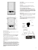
Wall Mounting
Optional metal and plastic enclosures are available for the
Series 340N2. The enclosure is rst attached to the wall using
fasteners through its mounting holes.
After wiring, the transmitter may be attached to the enclosure
with the terminal headers facing in using the slots in the Series
mounting anges. As an alternate mounting arrangement, the
340N2 may be fastened to the box cover using double-sided
adhesive tape.
Temperature Sensor Installation
The location of the temperature sensors with regard to the ow
sensor is important to the accuracy of the energy calculation.
Temperature sensor T1 must be located closest to the
ow sensor. A distance of 5 pipe diameters will give the
greatest accuracy. Always install the temperature sensor
downstream of the ow sensor.