
Owner's manual


4
N2+
N2-
REF
2 pmeT
1 pmeT
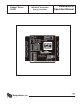
Model: 340N2
S/ N 340N2-XX X XX
W1
W2
FER
2N
-
2N
+
Mattapoisett, MA 027 39
11 22 33
Metasys
®
CPN, FAC,
or NCM
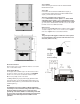
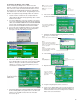
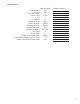
Sample wiring to N2 Network
If the Series 340N2 is connected at the beginning or the end of the N2 network, jumpers W1 and W2 can be shorted for
biasing and terminating of the network. The Series 340N2 biasing circuitry is shown in the diagram on the right.
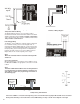
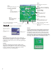
Thermistor Wiring Diagram
T emp 2
T emp 1
Ma
t
10KΩ Thermistors
Sample Pulse Output wiring Diagram
Temperature Element Wiring
The Badger Meter thermistors are not polarity sensitive.
Connect the thermistor closest to the ow sensor to the Series
340N2 terminal block marked Temp 1 number 3 and number
2. The other thermistor wires to Series 340N2 terminal marked
Temp 2 number 3 and number 2.
Pulse Output Wiring
The Badger
®
Series 340N2 has solid state switch output rated
for a maximum sinking current of 100 mA @ 36 VDC. In
most cases the Series 340N2 pulse out (+) will connect to the
unput pulse (+) and the Series 340N2 pulse out (-) terminal to
the input pulse (-) of the receiving device. The separate two
terminal removable header on the Series 340N2 is labeled
Output. Observe the electrical polarity of the output.
Note:
When the solid state switch is closed the red output LED
will turn on.
Connecting the N2 Bus
Observe polarity when connecting the Series 340N2. Connect
the N2+, N2- and Ref to the appropriate connections in the N2
network.
Note:
The Series 340N2 default address must be changed before
it is introduced into an existing network to avoid any pos-
sible address conicts. See programming instructions on
the following page.
Sample Sensor Wiring Diagram