Series 380 Impeller Btu System 380CS/HS IMPORTANT: This manual contains important information. READ AND KEEP FOR REFERENCE. PN: 880102-0001 Rev.
Series 380 Impeller Btu System Page ii 7-11
Installation & Operation Manual CONTENTS INTRODUCTION....................................................................................................................................................... 5 MECHANICAL INSTALLATION................................................................................................................................. 6 General..............................................................................................................................................
Series 380 Impeller Btu System Page iv 7-11
Installation & Operation Manual INTRODUCTION The Data Industrial® Series 380 Btu System from Badger Meter provides a low cost solution for metering cold or hot systems. The 380CS/HS can accurately measure flow and temperature differential to compute energy. Utilizing BACnet™ or Modbus® RS-485 communications protocols or a scaled pulse output, the Btu System can interface with many existing control systems. The rugged design incorporates an impeller flow sensor and two temperature probes.
Series 380 Impeller Btu System MECHANICAL INSTALLATION General The accuracy of flow measurement for all flow measuring devices is highly dependent on proper location of the sensor in the piping system. Irregular flow velocity profiles caused by valves, fittings, pipe bends, etc. can lead to inaccurate overall flow rate indications, even though local flow velocity measurement may be accurate.
Installation & Operation Manual COMMISSIONING All setup and commissioning of the Series 380 is done using a USB to Mini USB cable and the Badger Meter Series 380 commissioning software. Figure 2 shows the main setup screen. Flow and Energy rates and totals can be selected or a custom unit can be put in with the correct conversion factor. For the temperature sensors the user can select the units along with the calculation mode, i.e., T1>T2, Absolute, or T1
Series 380 Impeller Btu System RS-485 Network Configurations The RS-485 Section can be configured in two ways: -- Modbus -- BACnet The following sections explain each in detail. RS-485 Network Configurations– Modbus Figure 4: Comm Parameters - Modbus Select Modbus, to access the Modbus pull down menus. Select the Address, Bit Rate (Baud Rate) and Mode (RTU or ASCII). The Series 380 uses IEEE 754 Float - Data Located in “Read Holding Registers.
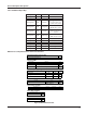
Installation & Operation Manual Modbus Register Map Series 380 Register Map Register Name Address Data Type Read/Write Sensor Temperature 40001 + 40002 IEEE 754 Float Read Only Remote Sensor 40003 + 40004 IEEE 754 Float Read Only Flow Rate 40005 + 40006 IEEE 754 Float Read Only Flow Total 40009 + 40010 IEEE 754 Float Read Only Energy Rate 40007 + 40008 IEEE 754 Float Read Only Energy Total 40011 + 40012 IEEE 754 Float Read Only Energy Calc Mode 40013 + 40014 IEEE 754 Float Rea
Series 380 Impeller Btu System Series 380 BACnet Object Map Description ID Name Units Analog Input AN1 TempIn ºC, ºF Analog Input AN2 TempOut ºC, ºF Analog Value AV1 VolFlow gpm, gph, lpm, lps, lph, ft3/s, ft3/m, ft3/h, m3/s, m3/min, m3/h, custom Analog Value AV2 EnergyFlow kBtu/min, kBtu/h, kW, MW, HP, Tons, custom Analog Value AV3 TotalVol gallons, galx100, galx1000, liters, ft3, m3, custom Analog Value AV4 TotEnergy Btu, kBtu, MBtu, kWh, MWh, kJ, MJ, custom Analog Value AV5
Specifications MECHANICAL Mass Manual < 15lb Sensor Assembly Installation & Operation Houseing: PEEK ELECTRICAL Impeller: 316SS SPECIFICATIONS Inputs Shaft: Tungston Carbide Torlon Bearing, EDPM O‐Rings Power 12‐35VDC CS Specific: Sensor Assembly: Ketron Bearing, Aflas O‐Rings 9‐28VAC rms HS Specific: Housing: PEEK Communication Modbus Impeller: 316SS Tee BACnet Shaft: Tungsten Carbide ® Cast Bronze Output CS Specific: Torlon Bearing, EDPM O-Rings HS Specific: Ketron® Bearing, Aflas® O-Rings Scal
Series 380 Impeller Btu System Sensor Body Sizes Tee Sizes: 0.75", 1", 1.25", 1.5", and 2" NPT Recommended Design Flow Range: 1 to 15 FPS Accuracy Flow Calculation: ±2% of flow rate within flow range ±0.
Installation & Operation Manual Intentional Blank Page 7-11 Page 13
Data Industrial is a registered trademark of Badger Meter, Inc. Other trademarks appearing in this document are the property of their respective entities. Copyright 2011, Badger Meter, Inc. All rights reserved. Please see our website at www.badgermeter.com for specific contacts. Due to continuous research, product improvements and enhancements, Badger Meter reserves the right to change product or system specifications without notice, except to the extent an outstanding contractual obligation exists.