Registers type ILR7XX and ILR7XXT AC_ILR_BA_02_1632 (October 2019) User Manual
Registers type ILR7XX and ILR7XXT CONTENT 1. Basic safety recommendations .......................................................................................................................................................................................... 1 2. Register operation................................................................................................................................................................................................................... 3 2.
Basic safety recommendations 1. BASIC SAFETY RECOMMENDATIONS Before installing or using this product, please read this instruction manual thoroughly. Only qualified personnel should install and/or repair this product. If a fault appears, contact your distributor. Before the first installation PLEASE FLUSH THE METER WITH FRESH WATER OR THE MEDIUM TO MEASURE BEFORE THE FIRST INSTALLATION. Installation Do not place any unit on an unstable surface that may allow it to fall.
Basic safety recommendations WARNING Failure to adhere to these safety instructions may result in damage to the product or serious bodily injury. RoHs Our products are RoHs compliant. Battery disposal The batteries contained in our products need to be disposed of as per your local legislation acc. to EU directive 2006/66/EG.
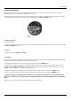
Register operation 2. REGISTER OPERATION The following describes register operation and program settings for the industrial oval gear series registers: Industrial Standard (ILR 700 / 701 / 701T), Pulse and Analog (750 / 750T). The register display consists of two rows of seven-segment digits, status, unit of measures, flow rate, and battery indicators. Operating function settings and programming are provided using the TOTAL and RESET buttons. Register display and button 2.
Register operation 2.4 Flow rate PER MIN is displayed in conjunction with the unit of measure. All flow rates are calculated in volume unit per minute. 2.5 Battery The "LBat" indicator will indicate when the battery is approaching end of life. When the indicator is illuminated, the 2/3AA, 3.0 VDC lithium battery is drained to 10% of its total capacity and should be changed. Normal battery life is five years. NOTE: A 2/3AA, 3.6 VDC battery may also be used as a replacement. Low battery indicator 2.
Register programming 3. REGISTER PROGRAMMING TO ENTER THE PROGRAMMING MODE, PRESS THE TOTAL BUTTON THREE TIMES AND THEN PRESS THE RESET BUTTON THREE TIMES (THE TIME LAG BETWEEN PRESSING BOTH BUTTONS SIX TIMES MUST BE WITHIN TWO SECONDS): In programming mode only, pressing and releasing the TOTAL button advances to the next parameter on the current screen. Pressing and releasing the RESET button changes the current flashing selection to another selection (such as “L” to “GAL”).
Register programming 3.3 Changing the meter pulse rate (for all ILR models with display) The meter pulse rate (screen is indicated by the “I” on the top row, on the left side) is the number of pulses per unit of measure as detected by the register. The pulse rate varies according to the type of attached meter. The bottom row consists of the 5digit integer value of the meter pulse rate, whereas the top row consists of the 2-digit decimal value of the meter pulse rate.
Register programming 1. Press the RESET button to toggle between available options (“I, for an inline-to-flow orientation and “P” for a perpendicularto-flow orientation or “o” for Remote versions and for the RCDL-nutating disc meters and the Vision turbine meters). 2. When finished adjusting the register orientation, press and hold the TOTAL button for one second to advance to the “Default Display” section. 3.
Additional programming: Industrial analog and industrial pulse (ILR750, ILR750T, ILR701, ILR701T) 4. ADDITIONAL PROGRAMMING: INDUSTRIAL ANALOG AND INDUSTRIAL PULSE (ILR750, ILR750T, ILR701, ILR701T) Output pulse lenght (for models ILR750 and ILR750T) Indicated by a “P” on the left hand side of the display, this screen allows the selection of the low duration of the output pulse.
Additional programming: Industrial analog and industrial pulse (ILR750, ILR750T, ILR701, ILR701T) 4.1 Pulse rate out (for model ILR750 and ILR750T) Indicated by an “o” on the left hand side of the display, this screen allows selection of the pulses output per liter or per gallon depending on unit of measure (0.01 PPL/PPG to 999 PPL/PPG). The meter pulse rate is entered in pulses per liter if the selected unit of measure is liters.
Additional programming: Industrial analog and industrial pulse (ILR750, ILR750T, ILR701, ILR701T) 4.3 Analog maximum flow rate (for models ILR750 and ILR750T) Indicated by a “H” on the left hand side of the display, this screen allows the setting of the flow rate that corresponds to the 20mA output: NOTE: • The maximum flow rate value must be greater than the minimum flow rate value. Default 30 LPM / 8 GPM To advance to the next programming screen, hold the TOTAL button.
Additional programming: Industrial analog and industrial pulse (ILR750, ILR750T, ILR701, ILR701T) Linearization point 9 (of 9) Number 9 at the left hand side of the display shows the 9th linearization point. The sample shows a flow rate of 250.0 liter per minute and a deviation of the flow meter of +0,15%. To correct this error, -0,15% needs to be set as correction. NOTE: • Minimum 3 linearization points needs to be programmed.
Register output specifications & wiring 5. REGISTER OUTPUT SPECIFICATIONS & WIRING 5.1 Pulse transmitter (model ILR 740) Pulse transmitter Orientation: The register must be mounted as delivered. The transmitter will not function if mounted differently. Transmitter wiring Reed switch outputs: Green and white. Ratings: Max power: 10W (not to exceed!); max. voltage: 200 VDC/peak AC; max. current: 0.5A DC/peak AC. Outputs: Raw reed switch output with no signal conditioning.
Register output specifications & wiring 5.2 Pulse and analog output (model ILR750 and 750T) Register wiring External DC+: Yellow External ground: Brown Pulse output: White Analog output: Green DC input: 8 to 24 VDC; 20 to 40mA Outputs: • Analog 4 to 20mA output; external load of 0 ohms to 250 ohms; flow rate is linear scaled between 4mA minimum and 20mA maximum set points. • Pulse output with internal pull-up resistor (1 KΩ); optional open collector output when the jumper is removed.
Return of goods for repair / Harmlessness declaration 6. RETURN OF GOODS FOR REPAIR / HARMLESSNESS DECLARATION Please refer to our claims return form/harmlessness declaration under https://www.badgermeter.de/en/service/return-of-goods.
October 2019 AC_ILR_BA_02_1632 Page 15
Page 16 AC_ILR_BA_02_1632 October 2019
October 2019 AC_ILR_BA_02_1632 Page 1
www.badgermeter.