® Badger Meter Europa GmbH Registers type ILR7XX and ILR7XXT INSTALLATION AND OPERATION MANUAL October 2016 AC_ILR_BA_02_1610
Contents Page 1. Basic safety recommendations ..................................................................................... 1 2. Register operation ........................................................................................................... 3 3. 4. 5. 6. 2.1. Normal operation .................................................................................................... 3 2.2. Status.....................................................................................
Basic safety recommendations Page 1/16 1. Basic safety recommendations Before installing or using this product, please read this instruction manual thoroughly. Only qualified personnel should install and/or repair this product. If a fault appears, contact your distributor. Before the first installation Please flush the meter with fresh water or the medium to measure before the first installation. Installation Do not place any unit on an unstable surface that may allow it to fall.
Basic safety recommendations Page 2/16 RoHs Our products are RoHs compliant. Battery disposal The batteries contained in our products need to be disposed of as per your local legislation acc. to EU directive 2006/66/EG.
Register operation Page 3/16 2. Register operation The following describes register operation and program settings for the industrial oval gear series registers: Industrial Standard (ILR 700 / 701 / 701T), Industrial Pulse (ILR 710 / 750 / 750T), Industrial Quadrature/Dual Pulse (ILR 720) and the Industrial Analog (ILR 730 / 750 / 750T). The register display consists of two rows of seven-segment digits, status, unit of measures, flow rate, and battery indicators.
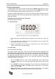
Register operation Page 4/16 To reset the resettable totalizer, press and hold the TOTAL button and then press and release the RESET button. To display 11-digit non-resettable totalizer, while the non-resettable total is displayed, press and hold the TOTAL button for seconds. The top row displays the 6 most significant digits; the bottom row displays five least-significant digits. NOTE: The non-resettable totalizer normally displays 5 least-significant digits. 2.4.
Register programming Page 5/16 3. Register programming In programming mode only, pressing and releasing the TOTAL button advances to the next parameter on the current screen. Pressing and releasing the RESET button changes the current flashing selection to another selection (such as “L” to “GAL”). To enter the programming mode, press the TOTAL button three times and then press the RESET button three times (the time lag between pressing both buttons six times must be within two seconds).
Register programming Page 6/16 NOTE: Error checking will not allow the user to advance to the next screen. 3.3. Changing the meter pulse rate (for all ILR models with display) The meter pulse rate (screen is indicated by the “I” on the top row, on the left side) is the number of pulses per unit of measure as detected by the register. The pulse rate varies according to the type of attached meter.
Register programming Page 7/16 1. Press the RESET button to toggle between available options (“I, for an inline-toflow orientation and “P” for a perpendicular-to-flow orientation or “O” for Remote versions and for the RCDL-nutating disc meters and the Vision turbine meters). 2. When finished adjusting the register orientation, press and hold the TOTAL button for one second to advance to the “Default Display” section. 3.5.
Additional programming: Industrial analog and industrial pulse Page 8/16 4. Additional programming: Industrial analog and industrial pulse (ILR 710 & ILR 730, ILR750, ILR750T, ILR701, ILR701T) Output pulse lenght (for models ILR 710, ILR750 and ILR750T) Indicated by a “P” on the left hand side of the display, this screen allows the selection of the low duration of the output pulse.
Additional programming: Industrial analog and industrial pulse Page 9/16 4.2. Analog minimum flow rate (for models ILR 730, ILR750 and ILR750T) Indicated by a “L” on the left hand side of the display, this screen allows the setting of the flow rate that corresponds to the 4mA output: NOTE: The minimum flow rate value must be less that the maximum flow rate value. • • • Minimum 0.0 LPM/GPM Maximum 100.0 LPM/GPM Default 0.
Additional programming: Industrial analog and industrial pulse Page 10/16 4.4. Linearisation (for models ILR701, ILR701T, ILR750 and ILR750T) Indicated by 1 – 9 on the left hand side of the display, followed by a hyphen (-), this screen allows the setting of the linearisation (in total 9 points). Figure 13: Linearisation point 1 (of 9) Press the TOTAL button to select a digit (selected digits flash). Press RESET to change the selected digit.
Register output specifications & wiring Page 11/16 5. Register output specifications & wiring 5.1. Pulse (model ILR 710) Register wiring External DC+: Yellow External ground: Brown Pulse output: White DC Input: 8 to 24 VDC; 20 to 40mA Outputs: Pulse output with internal pull-up resistor; optional open collector output with output jumper removal; pulse output is scalable in pulses per liter or pulses per gallon.
Register output specifications & wiring Page 12/16 5.2. Dual pulse (model ILR 720) Register wiring External DC+: Yellow External ground: Brown Pulse output 1: White Pulse output 2: Green External reset: Grey DC input: 8 to 24 VDC; 20 to 40mA Outputs: Dual-pulse output with internal pull-up resistor; optional open collector output with output jumper removed; dual pulse output forms a quadrature signal for direction of flow. Inputs: External reset pulled low to reset the batch totalizer.
Register output specifications & wiring Page 13/16 5.3. Analog (model ILR 730) Register wiring External DC+: Yellow External ground: Brown Analog output: White DC input: 8 to 24 VDC; 20 to 40mA Outputs: Analog 4 to 20mA output in loop powered configuration; external load of 50 ohms to 250 ohms; flow rate is linear scaled between 4mA minimum and 20mA maximum set points; flow rates below programmed minimum read 4mA.
Register output specifications & wiring Page 14/16 5.4. Pulse transmitter (model ILR 740) Figure 16: Pulse transmitter Orientation: The register must be mounted as delivered. The transmitter will not function if mounted differently. Transmitter wiring Reed switch outputs: Green and white. Ratings: Max power: 10W (not to exceed!); max. voltage: 200 VDC/peak AC; max. current: 0.5A DC/peak AC. Outputs: Raw reed switch output with no signal conditioning.
Register output specifications & wiring Page 15/16 5.5. Pulse and analog output (model ILR750 and 750T) Register wiring External DC+ : Yellow External ground : Brown Pulse output : White Analog output : Green DC input : 8 to 24 VDC; 20 to 40mA Outputs: - Analog 4 to 20mA output in loop powered configuration; external load of 50 ohms to 250 ohms; flow rate is linear scaled between 4mA minimum and 20mA maximum set points; flow rates below programmed minimum read 4mA.
Return of goods for repair / Harmlessness declaration 6. Return of goods for repair / Harmlessness declaration Please refer to our claims return form/harmlessness declaration under www.badgermeter.de/service/return of goods.
AC_ILR_BA_02_1610
Hotline Phone +49-7025-9208-0 or -46 Fax +49-7025-9208-15 ® Badger Meter Europa GmbH Subsidiary of Badger Meter, Inc., USA Nürtinger Strasse 76 72639 Neuffen (Germany) E-mail: badger@badgermeter.de www.badgermeter.