
Instructions


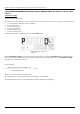
Table Of Contents
- 1. Basic safety recommendations
- 2. Register operation
- 3. Register programming
- 3.1 Changing unit of measure
- 3.2 Scale factor
- 3.3 Changing the meter pulse rate (for all ILR models with display)
- 3.4 Changing the register orientation (for all ILR models with display)
- 3.5 Changing the display mode (for all ILR models with display)
- 3.6 Exiting programming mode (for all ILR models with display)
- 4. Additional programming: Industrial analog and industrial pulse (ILR750, ILR750T, ILR701, ILR701T)
- 5. Register output specifications & wiring
- 6. Return of goods for repair / Harmlessness declaration

Additional programming: Industrial analog and industrial pulse (ILR750, ILR750T, ILR701, ILR701T)
Page 8 AC_ILR_BA_02_1632 October 2019
4. ADDITIONAL PROGRAMMING: INDUSTRIAL ANALOG AND INDUSTRIAL PULSE (ILR750, ILR750T, ILR701,
ILR701T)
Output pulse lenght
(for models ILR750 and ILR750T)
Indicated by a “P” on the left hand side of the display, this screen allows the selection of the low duration of the output pulse.
• “0” for zero milliseconds (pulse output is disabled)
• “2” for 2 milliseconds
• “10” for 10 milliseconds
• “20” for 20 milliseconds
• “40” for 40 milliseconds
• “100” for 100 milliseconds
To advance to the next programming screen, hold the TOTAL button.
Output pulse lenght screen
About Output Pulse Length: The pulse rate duration should take into account the "Pulse Rate Out" and maximum meter
flow rate, to prevent an output pulse duration greater than the required time between pulses. The Output Pulse Length
should be set to less than the value of “t.”
Per the equation:
Maximum meter flow rate (in GPM or l/m)
t = ----------------------------------------------------------------- x 1000
60X output pulse rate
where t = the required pulse rate in milliseconds.
The output pulse rate = the programmed parameter (default = 1.00 PPL/PPG)
The maximum meter flow rate = the maximum flow rate of the meter for the application.