
User's Manual

Installation
Data
BadgerMeter,Inc.
®
Model ADE™
Absolute Digital Encoder
ADE-I-01
P/N 64764-001 Rev. 1
9-03
IDENTIFICATION
The Badger Meter Absolute Digital Encoder (ADE) is available for all
remote and pit settings where a Badger Meter water meter can be
located. The ADE is permanently sealed to eliminate moisture, dirt, and
other contaminants to insure reliable operation in submerged or indoor
applications. As part of the foundation for Badger Meter's MRT
products, including ORION
®
, Badger
®
ERT
®
, BadgerTouch
TM
, and
other Badger approved AMR solutions, the ADE provides an output for
superior electronic resolution.
Available for all Recordall
®
Disc, Turbo, Compound and Fire Service
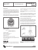
Meters, each ADE is clearly identified on the face of the dial with an
assembly number, unit of measure, and meter model (see figure 1.)
SUGGESTED TOOLS
59983-001 Gel-Splice Crimping Tool
59989-001 Coax Stripper
59991-001 Wire Cutting Pliers
59993-001 Wire Stripper
TORX
®
Driver
59987-001 VOM Multimeter (Analog) (OPTIONAL)
Before proceeding with installation, be certain that the meter type and
size correspond, and that the proper ADE configuration has been
supplied for the application.
REQUIRED MATERIAL
62084-001 Field Splice Kit
Contents: (3) 59761-001 Gel-Connectors
(2) 34776-001 Cable Ties
(1) 62085-001 Splice Enclosure
Figure 1. Identification
CONNECTING ADE
The ADE should only be connected to a Badger Meter approved
product. Connection to an unapproved product will void the
ADE warranty.
Your ADE will either have a factory installed two-conductor cable
(black) or a factory installed three-conductor cable (brown) for
connection to an AMR module.
If the wire is cut or broken on either a 2 or 3 wire ADE and requires a
field splice after initial installation, connect like color wires to maintain
proper installation.
To connect to an AMR module, strip approximately 1½” of outer
insulation sheath from the ADE and AMR module cables using the
59989-001 Coax Stripping Tool. Use caution in removing the outer
sheath so that the inner signal wire insulation is not damaged.
Unwind the outer foil shield from the ADE cable and cut it off even with
the outer sheath using the wire cutting pliers. For two conductor
cables, do not cut the uninsulated shield drain wire.
ADE WITH THREE WIRES (BROWN CABLE)
For connection to an ORION
®
Transmitter, verify the ADE has a brown
cable. Using the chart below, connect the ADE™ conductors to the
AMR module conductors using insulation displacement gel-filled
splices, P/N 59761-001 provided in the installation kit. Crimp the
cables completely using a parallel jaw crimper, P/N 59983-001.
For connection to an Itron
®
remote ERT
®
, verify that the ADE has a
brown cable and contains an ADE on the label. For more information
on the installation instructions for the Itron remote ERT, please refer
to Itron's Installation Remote ERT Modules 40W-1 and 50W-1.
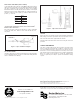
Figure 4. 3 Conductor RTR Splice Installation Diagram
If the wire is cut or broken and requires a field splice after
initial installation, connect like colors to maintain proper
installation.
ADE™ ORION
®
Itron
®
BadgerTouch
TM
Remote
Red Red Red White
Black Black Black White
Green Green Green N/A