Ellipse® Pitot Tube Meter PFA Fire Pump System 2500 2000 3000 GPM FM APPROVED 3500 1500 1000 PFA-XXX X inch 250 SWP X/XX S/N AXXXXXXX PTT-UM-00523-EN-02 (April 2014) 4000 F M VED PR AP O RS TE O ME ERS FLUJ OW ET F L B IT M R D E D E D ID O ME User Manual
Ellipse® Pitot Tube Meter, PFA Fire Pump System CONTENTS Introduction . . . . . . . . . . . . . . . . . . . . . . . . . . . . . . . . . . . . . . . . . . . . . . . . . . . . . . . . . . . . . . . . . . . . . . . . . 3 Specifications . . . . . . . . . . . . . . . . . . . . . . . . . . . . . . . . . . . . . . . . . . . . . . . . . . . . . . . . . . . . . . . . . . . . .
User Manual INTRODUCTION The Preso Model PFA Fire Pump System is FM-approved and features the Preso Ellipse primary flow sensor. The Preso patented elliptical design outperforms and provides greater accuracy than traditional differential pressure flow measurement devices. This differential pressure flow meter is designed with a series of ports facing the upstream velocity pressures, as well as flow sensing ports strategically located ahead of the trailing edge flow separation.
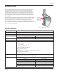
Ellipse® Pitot Tube Meter, PFA Fire Pump System PIPE ORIENTATION AND SENSOR MOUNTING FLOW 10° 10° FIELD WELD H FM L APPROVED L LIQUID FLOW METERS DEBITMETERS MEDIDOR DE FLUJO FM APPROVED FLOW METERS DEBITMETERS MEDIDOR DE FLUJO NNOTE: Pipe must remain full at all times during measurements.
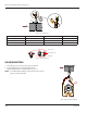
User Manual INSTALLATION INSTRUCTIONS, SINGLE SUPPORT 1. Choose the proper location to install the PFA Fire Pump System Ellipse using AGA/ASME standards (or equivalent). See “Preso Ellipse Location Instructions” on page 7. 2. Grind the surface of the pipe where the PFA Fire Pump System Ellipse is to be inserted to provide a clean area for welding. 3. Weld the supplied weld-o-let to the pipe using standard codes for your application (1/16" weld gap recommended).
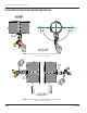
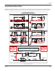
Ellipse® Pitot Tube Meter, PFA Fire Pump System L H L F M VED PRO AP RS TE O ME ER S FL UJ OW ET FL BI TM R DE DE DI DO ME H FIELD WELD FLOW Figure 5: Sensor alignment Pipe Size Model / Sensor Weld Connector Drill Bit 2"…5" PFA (1/2") 1/8" 3/8" 6"…12" PFA (7/8") 1/2" 1/2" 14"…16" PFA (1-1/4") 1" 7/8" Table 3: Double support drill bit size Ellipse Sensor Double Support Pin Guide Ring Figure 6: Double support pin GAGE MOUNTING 1. The FGE gage can be line, bracket or panel mounted.
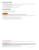
User Manual LOCATION INSTRUCTIONS Straight pipe requirements: Accuracy is affected by the piping configurations due to the disturbances of the flow profile. A fully developed symmetrical flow profile is achieved with the minimum upstream and downstream recommended lengths.
GAGE INSTALLATION 1. The connecting tubing between the PFA Fire Pump System and the gage should be as short as possible and should slope down a minimum of 1 inch per foot. 2. Secure and support the tubing to prevent sagging and/or vibration. 3. Make sure the head heights are even. 4. Run a bleed line from the gage vent valves to a pan or drain. GAGE OPERATION 1. Identify Hi and Lo pressure inlets on the gage. 2.