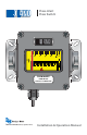
® Flow-Alert Flow Switch GPM OIL LPM FLOW-ALERT FLOW SWITCH 6000 PSI / 414 BARS MAX FORM #04-VAM-UM-00229 (September 2012) Installation & Operation Manual
I - INTRODUCTION The Flow-Alert flow meter combines the rugged proven technology of a direct reading, piston-type, variable area flow meter, coupled with electrical contacts utilized to signal at selected flow rates. This combination is sealed against industrial contamination by a NEMA 12 and 13 (IP52/54) rated enclosure. This product provides a local flow indication and automatically signals the operator or PLC if flow is too high or too low.
II - SPECIFICATIONS Enclosure Rating • NEMA 12 & 13 (equivalent to IP52 & 54) Temperature Range • -20 °F to +240 °F (-20 °C to +116 °C) Pressure Rating Aluminum/Brass • Liquids (¼” to 1½”): 3500 psi (241 bar) maximum with a 3:1 safety factor • Gases (¼” to 1½”): 1000 psi (69 bar) maximum with a 10:1 safety factor Pressure Rating Stainless Steel • Liquids (¼” to ½”): 6000 psi (414 bar) maximum with a 3:1 safety factor • Liquids (¾” to 1½”): 5000 psi (345 bar) maximum with a 3:1 safety factor • Gases (¼” to 1
Safe Operating Area for SPST (NO) 0.5 0.4 0.3 0.2 0.1 0.0 0 4 8 12 16 20 24 28 32 36 40 44 Safe Operating Area for SPST (NC) 0.6 Operating Current (DC Amps) Operating Current (DC Amps) 0.6 0.5 0.4 0.3 0.2 0.1 0.
III - INSTALLATION CAUTION Caution - This product should be installed and serviced by technically qualified personnel trained in maintaining industrial class flow instrumentation and processing equipment. CAUTION Caution - Read instructions thoroughly before installing the unit. If you have any questions regarding product installation or maintenance, call your local supplier for more information. CAUTION Caution - This meter may contain residual amounts of test fluid at the time of shipment.
INSTALLATION RECOMMENDATIONS The in-line flow meter is a simple device to install. However, the following measures are recommended for reliable, trouble-free operation: Do - Align pipe accurately. Piping should be accurately aligned and of correct length. The high pressure body of the flow meter can withstand shock and flow/pressure pulsation.
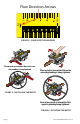
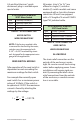
Don’t - Install the meter near fastacting valves. Fast-acting valves have the potential to create high magnitude hydraulic pressure spikes. These spikes can damage the internal components of the meter, resulting in inaccuracies or malfunction. Don’t - Allow unidirectional meters to be operated against the direction of the flow arrow. The standard flow meter is an unidirectional flow meter. The piston acts as a check valve to block flow in the reverse direction.
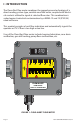
Flow Direction Arrows GPM OIL LPM FIGURE 4 - FLOW DIRECTION ARROWS GP M LP M GPM IL O rt le h M AX -A itc RS ow Sw BA Fl ow Fl I/2 41 PS 35 LP M 00 IL O 35 Place wrench on transmitter flats on the same side plumbing is being tightened rt AX le -A it ch M RS ow Sw BA Fl ow Fl I/2 41 PS 00 Place wrench on transmitter flats on the same side plumbing is being tightened GP M LP M IL O rt le h M AX -A itc RS ow Sw BA Fl ow Fl I/2 41 PS 35 00 GPM LP M O IL Never place wrench on transmitter f
A 4-pin Brad Harrison® quickdisconnect plug is available upon special order. 4-Pin Connector used with SPDT Micro Switch Red Black White Green Normally Closed (NC) Normally Open (NO) Common Ground TABLE 3 - 4-PIN CONNECTOR MICRO SWITCH WIRE DESIGNATIONS NOTE: If the factory supplied cable is removed for hard wiring the meter, switches must be connected with 0.187” × 0.020” insulated flag terminals designed for the appropriate wire gauge for the application.
IV - OPERATION WHITE BLACK Load Flow-Alert Power Line Power Line Wiring Configurations WHITE RED Load Flow-Alert Power Line Power Line Load will turn ON when flow exceeds setpoint. Load will turn OFF when flow exceeds setpoint. FIGURE 7 - WIRING CONFIGURATION FOR LOADS WITHIN Flow-Alert CONTACT RATINGS R 1 WHITE BLACK Flow-Alert Load Power Line Power Line Relay Coil R1 Load will turn OFF when flow exceeds setpoint.
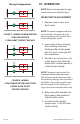
6. Install the cover gasket and front cover and secure with screws. To properly seat the cover gasket, tighten cover screws in a crisscross pattern as show in Figure 10. Latching Roller 1. Loosen the screw securing the switch assembly (Figure 11). 2. Slide the switch assembly until the arrow pointers on the switch band are aligned with the desired flow rate indicated on the scale. LPM Spacer Strip Switching Roller 3. Tighten the screw.
V. MAINTENANCE WARNING GPM Arrow Pointers on Switch Band LPM Screw Warning - Disconnect electrical power before removing meter cover. Failure to follow these instructions could result in serious personal injury or death and/or damage to the equipment. OIL SWITCH REPLACEMENT Micro Switch (Figure 13) FIGURE 11 - REED SWITCH ADJUSTMENT - ¼” MODELS 1. Disconnect cable connection to the meter. 2. Remove screws securing cover and remove cover.
gasket. To properly seat the cover gasket, tighten cover screws in a crisscross pattern as shown in Figure 10 on page 10. Reed Switch (Figure 14) 1. Disconnect the Hirschmann connector and remove connector from wires. 2. Remove screws securing cover and remove cover. 3. Remove the two scale mounting screws. 4. Remove the screws securing the two mounting brackets and remove the brackets. 5. Loosen the two slide bracket screws. 6.
3. Thoroughly wipe off the entire meter surface using mild detergent or isopropyl alcohol. Mounting Bracket Screws Mounting Bracket GPM LPM Strain Relief OIL Reed Switch Scale Mounting Screw Side Bracket Switch Mounting Screw FIGURE 14 - REED SWITCH REPLACEMENT Cartridge Cleaning (Figure 15) 1. Disconnect the meter cable. 2. Remove the meter from the line. Remove excess piping from meter.
9. Reassemble spring, then piston/magnet assembly and retaining ring into cartridge. 10. Gently push cartridge assembly into housing while holding the magnetic flow indicator in position. 11. Install metering cone/spider plate assembly, retaining spring, and secure with inlet fitting. 12. Reinstall meter to the line. Reconnect electrical power.
VI - APPENDIX APPLICATION INFORMATION - LIQUID Viscosity Effect (SUS/cSt) The design utilizes a precision machined, sharp-edged orifice and biasing calibration spring that assures operating stability and accuracy over the wide viscosity range common to many fluids. Generally, high flow models of each meter size provide good accuracy over a viscosity range of 40 to 500 SUS (4.2 to 109 cSt).
To adjust Pressures beyond (above or below) scale limits: Step 1. Locate point at which the brightly colored indicator line intersects the vertical 100 PSIG pressure line. Step 2. Divide this reading by the Pressure Correction Factor (f1) indicated in the Conversion Chart. To adjust for changes in Temperature : Step 1. Divide the 100 PSIG flow rate reading by the Temperature Correction Factor (f2). To adjust for changes in Specific Gravity: Step 1. Establish the square root of the new specific gravity.
DETERMINE FLOW RATES USING DIFFERENT PRESSURES & TEMPERATURES scfm ( actual ) = scfm ( indicated ) f1x f 2 x f3 Where f1 = Conversion Factor for Inlet Pressure f2 = Conversion Factor for Inlet Pressure f3 = Conversion Factor for Inlet Pressure Table 1 - Pressure Correction Factor (f1) Operating Pressure psig 25 50 75 100 125 150 175 200 225 250 BAR 1.7 3.5 5.2 6.9 8.6 10.4 12.1 13.8 15.5 17.2 kPa 172 345 517 689 862 1034 1207 1379 1551 1724 f1 1.700 1.331 1.131 1.
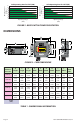
LIQUIDS Aluminum Brass T316 SST T303 SST Viton® EPR Polycarbonate Nylon Pyrex® Correction Factor Acetic Acid (Air Free) 1.06 0.909 0.971 C N R R R R C N R Acetone 0.79 1.053 1.125 R R R R N R N R R Alcohol Butyl (Butanol) 0.83 1.027 1.098 C C R R C R R R R Alcohol Ethyl (Ethanol) 0.83 1.027 1.098 C C R R C R R N R Ammonia 0.89 0.992 1.060 R C R R N R N C R Benzine 0.69 1.127 1.204 C R R C R N N R R Carbon Disulphide 1.
Specific Gravity Correction Factor Aluminum Brass T316 SST T303 SST Viton® EPR Polycarbonate Nylon Pyrex® GASES Air 1.0 1.000 R R R R R R R R R Argon (A) 1.38 1.175 R R R R R R R R R Carbon Dioxide (CO2) 1.53 1.237 R R R R R R R R R Freon 11 (CCI3F) 4.92 2.218 R R R R R R R R R Freon 12 (CCI2F) 4.26 2.060 R R R R R R R R R Helium (HE) 0.14 0.374 R R R R R R R R R Hydrogen (H2) 0.07 0.
FLOW VS. PRESSURE DROP PRESSURE DROP, PSI .10-1.0 .02-.20 .05-.50 1-15 1-10 0.5-5.0 0.1-1.0 0.2-2.0 FLOW, GPM FLOW, GPM 1-1/4"/1-1/2" 3/4"/ 1" PRESSURE DROP, PSI PRESSURE DROP, PSI 4-40 3-30 2-20 10 5 0 1-10 0.5-5.0 0.2-2.0 0 10 10-100 10-75 5-50 3-30 FLOW, GPM FLOW, GPM 3/4"/1" Reverse Flow 1-15 1-10 0.5-5.0 0.1-1.0 3-30 2-20 0.2-2.0 FLOW, GPM 1-1/4"/1-1/2" Reverse Flow 4-40 PRESSURE DROP, PSI PRESSURE DROP, PSI 1/2" Reverse Flow 0.2-2.0 10-150 5-50 0.5-5.
0.20-2.0 1/4" 1/2" 1-15 6 PRESSURE DROP, PSI PRESSURE DROP, PSI 0.10-1.0 .02-.20 .05-.50 4 2 0 0.0 1-10 0.5-5.0 2 0 0.5 FLOW, GPM 5-50 PRESSURE DROP, PSI 2-20 4 1-10 0.2-2.0 2 1-15 10-100 5-50 3-30 0 1 2 3 4 5 FLOW, GPM 3/4"/1" Reverse Flow PRESSURE DROP, PSI PRESSURE DROP, PSI 10-150 10-75 FLOW, GPM 1-1/4"/1-1/2" Reverse Flow 4-40 3-30 2-20 0.5-5.0 0.1-1.0 2 2.5 PRESSURE DROP, PSI PRESSURE DROP, PSI 0.5-5.0 6 0 0.2-2.
1/2" PRESSURE DROP, PSI PRESSURE DROP, PSI 0.2-2.0 .05-.50 1-10 0.5-5.0 0.1-1.0 0.2-2.0 10-100 10-75 5-50 3-30 20-275 3-30 2-20 0.5-5.0 0.1-1.0 0.2-2.0 FLOW, GPM 1-1/4"/1-1/2" Reverse Flow 4-40 PRESSURE DROP, PSI 1-10 FLOW, GPM 3/4"/1" Reverse Flow 1-15 1-10 0.2-2.0 20-180 FLOW, GPM 1/2" Reverse Flow 0.5-5.0 2-20 PRESSURE DROP, PSI 10-150 PRESSURE DROP, PSI 4-40 3-30 FLOW, GPM 3" 1-1/4"/ 1-1/2" PRESSURE DROP, PSI 5-50 FLOW, GPM FLOW, GPM 0.2-2.
1/4" 1/2" .20-2.0 PRESSURE DROP, PSI PRESSURE DROP, PSI .10 -1.0 0.2-2.0 .05-.50 1-15 1-10 0.5-5.0 0.1-1.0 0.2-2.0 FLOW, GPM FLOW, GPM 1-1/4"/ 1-1/2" 5-50 4-40 3-30 0.5-5.0 2-20 1-10 0.2-2.0 10-150 PRESSURE DROP, PSI PRESSURE DROP, PSI 3/4" / 1" 10-100 10-75 5-50 3-30 FLOW, GPM FLOW, GPM WATER 1/2" .20-2.0 .10 -1.0 PRESSURE DROP, PSI PRESSURE DROP, PSI 1/4" 1-15 1-10 0.5-5.0 0.2-2.0 FLOW, GPM FLOW, GPM PRESSURE DROP, PSI 4-40 3-30 0.5-5.0 2-20 0.1-2.
20 20 PRESSURE DROP, PSI 1-10 10 5 0.
NOTES Page 26 Form #04-VAM-UM-00229 09/12
Badger Meter Warranty ® Flow-Alert Flow Switch PRODUCTS COVERED been subject to vandalism, negligence, accident, acts of God, The Badger Meter warranty shall apply to the Hedland Flow- circumstances which are beyond the reasonable control of Alert Flow Switch (“Product”). Badger Meter.
Trademarks appearing in this document are the property of their respective entities. Due to continuous research, product improvements and enhancements, Badger Meter reserves the right to change product or system specifications without notice, except to the extent an outstanding contractual obligation exists. © 2012 Badger Meter, Inc. All rights reserved. info@hedland.com | www.hedland.com | www.badgermeter.