
Manual

Page 10 Form #04-VAM-UM-00229 09/12
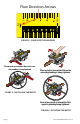
Wiring Congurations
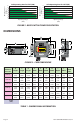
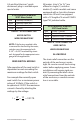
Load will turn ON when ow exceeds setpoint.
Load will turn OFF when ow exceeds setpoint.
BLACK
Flow-Alert
WHITE
Power Line
Power Line
Load
RED
Flow-Alert
WHITE
Power Line
Power Line
Load
FIGURE 7 WIRING CONFIGURATION
FOR LOADS WITHIN
FLOWALERT CONTACT RATINGS
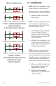
BLACK
Flow-Alert
WHITE
R
1
Load
Relay
Coil
R1
Power Line
Power Line
BLACK
Flow-Alert
WHITE
R
1
Load
Relay
Coil
R1
Power Line
Power Line
Load will turn OFF when ow exceeds setpoint.
Load will turn ON when ow exceeds setpoint.
FIGURE 8 WIRING
CONFIGURATION FOR LOADS THAT
EXCEED FLOWALERT
CONTACT RATINGS
IV OPERATION
NOTE: Refer to the Appendix for appli-
cation information and uid charts.
MICRO SWITCH ADJUSTMENT
1. Remove cover screws and
front cover.
NOTE: On meters equipped with dual
micro switches, the right-side is the
decreasing ow switch; the left-side is
the increasing ow switch.
2. Loosen the screws securing
the switching roller and
latching rollers to the guide
bar. Turn each screw one full
turn maximum.
3. All rollers are secured as a set
to the spacer strip. Slide the
entire roller set until pointer is
at the desired setting.
NOTE: The spacer strip controls the
maximum distance between rollers.
This distance may be shortened when
the switching setting is close to the end
of the ow scale. Latching rollers may
also be removed if the switching set-
ting is close to the end of the ow scale.
4. Make sure roller brackets are
ush against the guide bar.
Tighten roller screws.
5. For dual switch models,
repeat steps 1-4 for left-side
switch setting.