
Manual


Form #04-VAM-UM-00229 09/12 Page 11
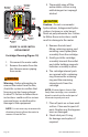
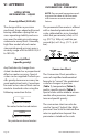
6. Install the cover gasket and
front cover and secure with
screws. To properly seat the
cover gasket, tighten cover
screws in a crisscross pattern
as show in Figure 10.
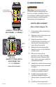
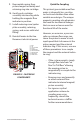
LPM
Latching Roller
Spacer Strip
Switching Roller
Latching Roller
Pointer
Guide Bar
FIGURE 9 SNAP SWITCH
ADJUSTMENT
FLOW-ALERT
FLOW SWITCH
6000 PSI / 414 BARS MAX
GPM LPM
OIL
1
2
3
4
FIGURE 10 COVER SCREW
TIGHTENING SEQUENCE
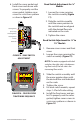
Reed Switch Adjustment for ¼”
Models
1. Loosen the screw securing
the switch assembly (Figure
11).
2. Slide the switch assembly
until the arrow pointers on
the switch band are aligned
with the desired ow rate
indicated on the scale.
3. Tighten the screw.
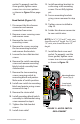
Reed Switch Adjustment for ¼” to
1½” Models
1. Remove cover screws and front
cover.
2. Loosen the screw securing the
switch assembly (Figure 12).
NOTE: On meters equipped with dual
switches, the right-side is the decreas-
ing ow switch; the left-side is the
increasing ow switch.
3. Slide the switch assembly until
the arrow pointer aligns with
the desired ow rate indicated
on the scale.
4. Tighten the screw.
5. For dual switch models, repeat
steps 1-4 for left-side setting.
6. Install the front cover and gas-
ket. To properly seat the cover
gasket, tighten cover screws in
a crisscross pattern as shown in
Figure 10.