
Manual


Form #04-VAM-UM-00229 09/12 Page 15
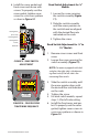
9. Reassemble spring, then
piston/magnet assembly and
retaining ring into cartridge.
10. Gently push cartridge
assembly into housing while
holding the magnetic ow
indicator in position.
11. Install metering cone/spider
plate assembly, retaining
spring, and secure with inlet
tting.
12. Reinstall meter to the line.
Reconnect electrical power.
LPM
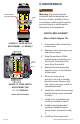
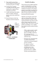
[1] - BODY
[2] - CAP
[3] - CONE ASSEMBLY
[4] - PISTON
[5] - INNER MAGNET
[6] - INDICATOR MAGNET
[7] - RETAINIGN RING
[8] - WAVE SPRING
[9] - METER SPRING
[1]
[9]
[5]
[6]
[4]
[7]
[3]
[8]
[2]
FIGURE 15 CARTRIDGE
COMPONENTS
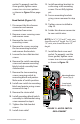
Quick Re-Coupling
This piston-type variable area ow
meter is inherently less sensitive
to shock and vibration than other
variable area designs. The unique
magnetic coupling also eliminates
the need for mechanical linkages
that can wear or loosen over the
functional life of the meter.
However, on occasion, a pressure
spike or extreme ow surge can
cause the piston to move at such
rapid speed that it disconnects the
piston magnet and the external
indicator ring. If this occurs, use one
of these procedures to re-couple
the magnet and the external indica-
tor ring:
• If the system permits, simply
change ow rate from “no
ow” to “full ow” allowing
the moving piston to
magnetically re-couple to the
indicator ring.
• Remove cover and manually
re-attach external ow
indicator to internal magnet/
piston assembly.
• For rigorous cyclical
applications where de-
coupling may occur
frequently, consult the
technical services sta for
further recommendations.