
Manual


Page 16 Form #04-VAM-UM-00229 09/12
VI APPENDIX
APPLICATION
INFORMATION LIQUID
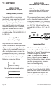
Viscosity Eect (SUS/cSt)
The design utilizes a precision
machined, sharp-edged orice and
biasing calibration spring that as-
sures operating stability and accu-
racy over the wide viscosity range
common to many uids. Generally,
high ow models of each meter
size provide good accuracy over a
viscosity range of 40 to 500 SUS (4.2
to 109 cSt).
Density Eect
(specic gravity)
Any uid density change from
stated standards has a proportional
eect on meter accuracy. Special
scales can be supplied if actual spe-
cic gravity decreases accuracy be-
yond application limits. Corrections
for more or less dense uids can be
made to standard scales using the
following correction factor:
10.
Specic Gravity
for water/water-based meters
0 876.
Specic Gravity
for petroleum-based meters
APPLICATION
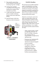
INFORMATION PNEUMATIC
NOTE: Pressure and temperature read-
ings must be taken at the ow meter
inlet to ensure accurate correction
factors.
The pneumatic ow meter is oered
with a standard graduated dual
scale, calibrated for air in standard
cubic feet per minute (scfm) at 1.0
s.g. (70 °F @ 100 psi), and liter per
second (lps) at 1.0 s.g. (21 °C @ 6.9
bar).
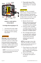
PRESSURE
SOURCE
FLOW
METER
AIR BLEED OFF
TO EQUIPMENT
ADJUSTABLE
VALVE
PRESSURE
GAUGE TEMP
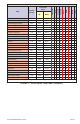
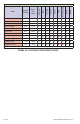
Conversion Chart
The Conversion Chart provides a
series of simplied mathematical
formulas to “correct” the graduated
scale for changes in pressure
(Table 1), temperature (Table 2),
and/or specic gravity (Table 3).
Special scales can be made to accom-
modate other pressures, tempera-
tures and specic gravity.
The conversion chart can also be
used to “correct” (adjust) the Multi-
pressure Flow Scale to indicate ow
rates in applications beyond the
parameters stated on the scale.