
Manual

Form #04-VAM-UM-00229 09/12 Page 7
Don’t - Install the meter near fast-
acting valves. Fast-acting valves
have the potential to create high
magnitude hydraulic pressure
spikes. These spikes can damage
the internal components of the
meter, resulting in inaccuracies or
malfunction.
Don’t - Allow unidirectional meters
to be operated against the direc-
tion of the ow arrow. The standard
ow meter is an unidirectional ow
meter. The piston acts as a check
valve to block ow in the reverse
direction. This causes an excessive
pressure dierential, which can
result in damage to internal meter
components. The ow meter is
also available in a modied design,
which oers a reverse ow by-pass
feature to accommodate bi-direc-
tional ow.
NOTE: In-line meters with a reverse
ow by-pass feature are available. Con-
sult factory for details.
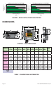
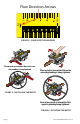
INSTALLING THE FLOWALERT
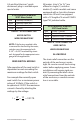
1. See Figure 4. Mount the meter
so uid is traveling in the
direction of the ow arrow.
2. See Figure 5. Select a mounting
location that is suitable for
viewing and product service. To
connect the ow meter into the
piping system, place an open-
ended wrench onto the ow
meter wrench ats adjacent
to the pipe connection being
installed. DO NOT wrench on
the opposite end of the ow
meter or leakage may result.
3. See Figure 6. After installation,
rotate meter by hand to view
ow scale.
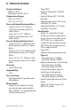
ELECTRICAL CONNECTIONS
Micro Switch
Equipped Models
All meters (size ¼” to 1½”) are of-
fered in single (1) switch or double
(2) switch models. The single switch
model is equipped with a 34” length
of 4-wire #18 AWG type SO jacketed
cable. The double switch model is
equipped with a 18” length of 7-wire
#16 AWG type SO jacketed cable.
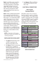
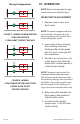
One Switch 4-Wire Cable
Red Normally Closed (NC)
Black Normally Open (NO)
White Common
Green Ground
Two Switch 7-Wire Cable
Switch 1
Red Normally Closed (NC)
Black Normally Open (NO)
White Common
Switch 2
Orange Normally Closed (NC)
Blue Normally Open (NO)
White/Black Common
Green Ground
TABLE 2 MICRO SWITCH
WIRE DESIGNATIONS