
User's Manual


TOOLS AND MATERIAL
Required Tools
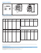
62658-000 Torx® Screw Driver (10 and 15 bits)
Suggested Tools
• Electric drill
• 3/16" carbide tip masonry drills
• Common and Phillips Screwdrivers T-25 Wire Stapler and Staples
• Touch reading device for installation verification
Required Material
63705-003 BadgerTouch Installation Kit for Remote
Applications, including:
• (2) 55211-231 Screw, Phillips Head
• (2) 62359-001 Screw Anchor 10-12 (1/4" drill bit required)
• (2) 34776-001 Cable Tie
Optional Material
56088 GE RTV-162 Adhesive Sealant
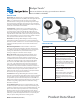
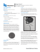
IDENTIFICATION
BadgerTouch Remote Modules are supplied as standalone
modules for field connection to High Resolution Encoder (HRE) or
Absolute Digital Encoder (ADE®) for all Recordall® Disc, Turbo,
Compound, Combo, and Fire Series meters and assemblies. Each
HRE or ADE is clearly identified on the face of the dial with an
assembly number, unit of measure and meter model number The
BadgerTouch Remote Module does not contain an identification
number. The HRE or ADE register contains a unique identification
number. The number is shown on the underside of the register
cover. Interrogation of the HRE or ADE will display the ID number
and the meter reading.
Figure 1: Identification – Touch Module
INSTALLATION
Unpacking
Carefully remove the BadgerTouch Remote Module (Figure 1) from
the shipping carton. Locate the corresponding HRE or ADE for
proper coordination during installation. Retain the contents of the
installation kit for use in making connections to the HRE or ADE
transmission line.
Location
To ensure proper operation of the BadgerTouch on-site meter
reading system, the BadgerTouch Pit Module should be mounted
through a predrilled hole in the pit lid. Minimum hole diameter
required is 1-3/4". The Pit Module contains electronic circuitry that
is totally encapsulated to enhance reliable performance in most
locations, under most conditions.
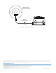
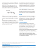
Remote Module Installation
The remote module contains two screw terminals that require
connection to the red and black lead wires of the HRE or ADE cable.
The BadgerTouch system is not polarity sensitive.
Red Wire
Black Wire
Te rminals
Green Wire
Wire
Access
Po rts
Figure 2: Remote Module Connection
Locate the position of the two mounting holes on the outside of the
building by using the remote module as a template. The Remote
Module should be located in an easily accessible location but
should be within 75 feet maximum wire distance to the water meter
and the encoder using Belden 9770 wire. Additional wire length and
other wire types may affect performance.
Drill a 3/16" wire entry hole at a suitable location in the building
wall. Cut the protective gel cap off the end of the HRE or ADE cable.
Feed the HRE or ADE cable from the water meter through the wall.
Then cut the cable to proper length, making sure you have sufficient
wire to make the connection to the Remote Module.
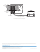
Wire access to the Remote Module may be from the rear, or through
a bottom or top access port. When utilizing rear access, allow
approximately 8" of extra cable behind the Remote Module to
facilitate making the wiring connections. If using the bottom or top
access port, the thin plastic area of the outer shroud needs to be
snapped off to expose the wire access port. Use a small wire cutting
pliers to snap the plastic.
BadgerTouch®
Automated Meter Reading System Remote Module
Models HREBT and ADEBT
BTA-UM-00232-EN-04 (June 2013)
Installation Data