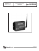
Badger® Model 345WT BadgerMeter, Inc.
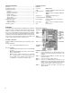
Table of Contents Overview............................................................................... 2 Installation Checklist............................................................. 2 Hardware Overview.............................................................. 2 Features........................................................................... 2 Electrical Connections...................................................... 2 Hardware Connection....................................................
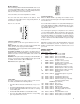
Modbus Address Before the Badger® Data Industrial® Model 345WT can be used, you must set the Modbus address. This address must be unique among all Modbus devices in the system including all devices that are connected on remote wireless links. Select an address, and set the dipswitches to match. The sum of the value of the switches is the address. In the example to the right, address 52 is set by placing switch 4, 16 and 32 to the on position.
Register Functions Pulse Count: The pulse count is stored as an unsigned 32bit integer. This allows for 2^32 pulses (4.2billion) to be counted before rollover. On Modbus systems that do not allow you to read 32 bit values, you can calculate the pulse count as follows: count = (MSW * 65535) + LSW Step 3: Set the following dip switches: Prog Enable = on ProgRstEn = on 485/232 = on Step 4: Power up the Model 345WT. The Green Alive LED should light up and stay on solid. Step 5: Run the LPC2000 Flash Utility.