
Manual

2
TABLE OF CONTENTS
Overview .............................................................................. 2
Installation Checklist ............................................................ 2
Hardware Overview ............................................................. 2
Features .......................................................................... 2
Electrical Connections ..................................................... 2
Hardware Connection ...................................................... 2
Modbus Address .............................................................. 3
System Configuration ...................................................... 3
Status LEDs .................................................................... 3
Signal Strength Test......................................................... 3
Modbus Overview ................................................................ 3
Register Listing ................................................................ 3
Register Functions .......................................................... 4
Firmware Update ................................................................. 4
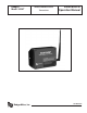
OVERVIEW
The Badger
®
Data Industrial
®
Model 345WT wireless Modbus/
pulse transceiver is designed to allow systems integrators the
ability to communicate with remote locations while avoiding
the costs associated with running low voltage wiring to multiple
locations in a single or between multiple buildings. To meet these
requirements, the Model 345WT provides the installer with all
the tools necessary to install and configure the hardware and
software with a minimum of time and investment.
Installation Checklist
A Model 345WT system installation has the following compo-
nents:
Required hardware
• TwoormoreModel345WTtransceivers.
External hardware
• RS485ModbusmastersystemsuchasaModel3700
or a PLC.
• Optional:RS485/Modbusslavedevicessuchaspower
meters or IO modules.
• Optional: Pulse output transducers for measuring
gas, electricity, water, etc. from existing meters and
sensors. Make sure to obtain the pulse output scale,
or multiplier for each device you will be using.
Hardware Overview
Features
Processor 60MhzARM7.
LED 2xRF,2xRS485,2xpulse,Alive,Alarm
Communications RS485Modbus
RF 900MhzFrequencyHopping,ISMband,
100mw
Rangeupto 1500ftindoordependingon
obstructions
PowerRequirement110-120VAC
PowerSupply Included,9VDC,class2transformer
(included)
Pulse Inputs 2x dry contact (consumption/rate/min/
max)
Size 6.5"x4.5"x2"
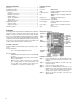
Electrical Connection
Hardware Connection
Step 1 - Unpack materials: Remove all materials from ship-
ping box and verify all required components are
available.
Step 2 - Mount the Model 345WT on the wall or other ap-
propriate location.
Step 3 - Connect the pulse output devices.
Step 4 - Connect the RS485 Modbus terminals to your
Modbus devices. This can include either the master
devicesuchasanModel3700orPLC,anditcan
include a slave device such as a power meter.
Step 5 - Attach the antenna and power connector to the
Model 345WT.