
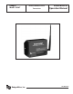
Manual

3
Modbus Address
Before the Badger
®
Data Industrial
®
Model 345WT can be used,
you must set the Modbus address. This address must be unique
among all Modbus devices in the system including all devices
that are connected on remote wireless links.
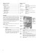
Select an address, and set the dipswitches to match.
The sum of the value of the switches is the address. In the
example to the right, address 52 is set by placing switch 4, 16
and 32 to the on position.
Note: 4 + 16 + 32 = 52
System Configuration
For most systems, set all of the system switches to the “off”
position.
Radio channel: This option selects the channel number that
can be used to isolate a group of Model 345WTs.
Programming: Set the Prog Enable and Prog RST En to Off
for normal operation.
Port RS232 or RS485: Set the switch to the Off position for
RS485operation.TheModel345WTcancommunicateviathe
RS232 connection, however, most Modbus devices will need
485terminals.
Baud Rate: This option sets the serial port speed for the Modbus
devices connected to the Model 345WT. Set this option to Off
for19200.SettheswitchtoOnfor9600baud.
Reserved: Set this option to Off.
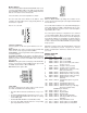
Status LEDs
The device should power up and be ready in a few seconds.
The LEDs should blink in the following manner.
•
The Alive LED should start to blink about once per sec-
ond.
•
The Alarm LED will blink when transmission errors occur.
• The RF TX/RX LEDs will blink when the radio is receiving
or transmitting data.
•
TheRS485LEDswillblinkforlocalModbusactivity.
• The Pulse input LEDs will light when the corresponding
pulse input terminals are closed.
Signal Strength Test
When the Model 345WT is operating, the Test button can be
used to report the signal strength received by the Model 345WT
from another unit.
Press and hold the Test button. The status LEDs will light up as
abargraphdisplay.EachLEDisapproximately10%ofscale.
For example if PULSE 1 and 2 are on, the received strength is
approximately20%to29%.
For useful signal reporting, it is important to turn off all but
one other Model 345WT. When reporting the signal strength,
the most recent wireless transmission received is displayed.
If two Model 345WTs are transmitting, the display will only
show the most recently received packet, and the user will not
be able to determine which Model 345WT the signal strength
being reported.
NOTE: The normal operation of the Model 345WT is suspended
while the test button is pressed. No pulses are counted,
Modbus communications and wireless transmissions are not
processed.
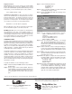
MODBUS OVERVIEW
Register Listing
offset point type desc
0 40001 UINT32 pulsecount1MSW
1 40002 UINT32 pulsecount1LSW
2 40003 UINT32 pulsecount2MSW
3 40004 UINT32 pulsecount2LSW(sameformat
as pulse count 1)
4 40005UINT16 instpulse1time(seconds)
5 40006UINT16 instpulse2time(seconds)
6 40007UINT16 (R/W)minpulse1time(seconds)
(write clears min/max)
7 40008UINT16 (R/W)minpulse2time(seconds)
8 40009UINT16 (R/W)maxpulse1time(seconds)
9 40010UINT16 (R/W)maxpulse2time(seconds)
10 40011UINT16 (R/W)instpulsecountsize.
(default 5)
100 40101 UINT16 SerialNumber(bytes1,2)(serial
number)
101 40102 UINT16 SerialNumber(bytes3,4)
102 40103 UINT16 SerialNumber(bytes5,6)
103 40104 UINT16 rmwareversion(e.g.v1.03,high
byte=major, lowbyte=minor,
0x8000agsetforBeta)
104 40105 UINT16 bootcount
105 40106 UINT32 mfgdateMSW
106 40107 UINT32 mfgdateLSW
107 40108 UINT16 radiogroupidsetting(0-6)
108 40109 UINT16 alarmags(0x01=bootfrom
watchdog)
109 40110 UINT16 maxpacketbuffersused.
110 40111 UINT32 Radiouptime(seconds)MSW
111 40112 UINT32 Radiouptime(seconds)LSW