Industrial Meters Oscillating Piston, Model OP Chemical & Sanitary, Sizes 1/2", 1", 2" OPM-UM-00291-EN-02 (August 2013) User Manual
Industrial Meter, Oscillating Piston, Sizes 1/2" through 2" Model OP Page ii August 2013
User Manual CONTENTS SCOPE OF THIS MANUAL . . . . . . . . . . . . . . . . . . . . . . . . . . . . . . . . . . . . . . . . . . . . . . . . . . . . . . . . . . . . . . . . .5 Description . . . . . . . . . . . . . . . . . . . . . . . . . . . . . . . . . . . . . . . . . . . . . . . . . . . . . . . . . . . . . . . . . . . . . . .5 INSTALLATION . . . . . . . . . . . .
Industrial Meter, Oscillating Piston, Sizes 1/2" through 2" Model OP Page iv August 2013
User Manual SCOPE OF THIS MANUAL This manual contains information concerning the installation, operation and maintenance of Badger oscillating piston meters. To ensure proper performance of the meters covered, the instructions given in this manual should be thoroughly understood. Retain the manual in a readily accessible location for future reference.
Industrial Meter, Oscillating Piston, Sizes 1/2" through 2" Model OP INSTALLATION Unpacking and Inspection To avoid damage in transit, Badger oscillating piston meters are shipped to the customer in a special shipping container. Upon receipt of the meter, perform the following unpacking and inspection procedures. If damage to the shipping container is evident upon receipt of the meter, request the carrier to be present when the meter is unpacked. 1.
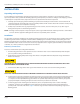
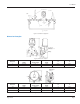
User Manual FLUSHING SYSTEM INLET CUTOFF VALVES CUTOFF VALVES FLUSHING SYSTEM OUTLET STRAINER BY-PASS SYSTEM Figure 2: Installation Configuration Dimension Examples 4 5/8 Dia. Holes Equally Spaced on 3 1/8 Dia. B.C. 150# F.F. 1" Flange with F.F. Flanges Figure 3: Dimensions example 1 Meter Size A Height 1" 18-15/16" 2" 19-13/32" B Laying Length C Depth D E 11" 8-1/8" 3-7/8" 2-7/8" 12-5/8" 10-1/16" 5-5/8" 3" D E 4 5/8 Dia. Holes Equally Spaced on 2 3/8 Dia. B.C. 1 3/8 Dia.
Industrial Meter, Oscillating Piston, Sizes 1/2" through 2" Model OP Installing the Meter The oscillating piston meters are designed for in-line installation. Examples of dimensions of the meter models, including laying lengths, are shown in "Figure 3". After reviewing the applicable dimension requirements, perform the following procedures: 1. Install appropriate mating connectors in pipeline. Provide proper gap length for meter.
User Manual OPERATING INSTRUCTIONS General Operating Instructions The instructions for operating an oscillating piston meter depend on the meter-accessory combination and the type of flow control devices used in the facility piping. In general, the operation is either manually controlled or accessory controlled.
Industrial Meter, Oscillating Piston, Sizes 1/2" through 2" Model OP MAINTENANCE General This section contains information for servicing and maintaining of the meter. The information consists of preventive maintenance, calibration and adjustment and general servicing procedures. Instructions for ordering replaceable parts and assemblies are provided in an Illustrated Repair Parts Bulletin that is included with this manual.
User Manual Change Gear Corrections If the accuracy test of a meter-accessory combination that incorporates change gears indicates that adjustment is required, perform the following procedures. 1. See the Parts List for the location of the calibrating change gears. 2. Determine the number of teeth and the outside diameter of the existing change gears. NNOTE: The number of teeth and the outside diameter are stamped on each gear. 3.
Industrial Meter, Oscillating Piston, Sizes 1/2" through 2" Model OP 2. Inspection a. Carefully examine the piston for warpage, cracks or other signs of wear and deterioration. Replace piston, if necessary. b. Check the magnet assembly and magnet assembly bushing (located on center pin inside chamber) for excessive wear and corrosion. Replace, if necessary. c. Check the control roller and control roller bushing. Replace, if necessary. d. Inspect the housing cover O-ring for wear and deterioration.
User Manual Angle Drive Gear Train (1" and 2" Meters Only) 1. Removal a. Remove the accessory device from the right-angle drive gear train. b. Remove the three acorn nuts securing angle drive gear train to the rear of meter housing and carefully pull the gear train the from locating studs. 3. Inspection a. Check that the gear train operates freely when the follower magnet is rotated. b. Check the magnet-spindle assembly, thrust bearing, worm gear, drive spindle and bushings for wear and corrosion.
Industrial Meter, Oscillating Piston, Sizes 1/2" through 2" Model OP SPECIFICATIONS Minimum Flow Rate, Q Minimum Continuous Operating Maximum Rate Short Duration Maximum Flow, Q Maximum 1/2" 1.5 gpm 4 gpm 6 gpm 1" 5.5 gpm 20 gpm 30 gpm 2" 25 gpm 65 gpm 100 gpm 150* psi ANSI 16.5 150 psi ANSI 16.5 150 psi ANSI 16.5 Continuous operation is acceptable at these rates, but accelerated wear of the piston and/or bushings may occur.
User Manual INTENTIONAL BLANK PAGE August 2013 Page 15
Trademarks appearing in this document are the property of their respective entities. Due to continuous research, product improvements and enhancements, Badger Meter reserves the right to change product or system specifications without notice, except to the extent an outstanding contractual obligation exists. © 2013 Badger Meter, Inc. All rights reserved. www.badgermeter.