Aurora243 Outdoor gNB Installation Guide All rights reserved © Baicells Technologies Co., Ltd.
About This Document This document is intended for personnel who will be installing the Baicells Aurora243 outdoor integrated 2x5 watts gNB product. The product overview is followed by the procedures for properly installing. Please be advised that only personnel with the appropriate electrical skills and experience should install this device. This document suits for the models of BSC7048A243 gNB. Copyright Notice Baicells Technologies, Inc., copyrights the information in this document.
Safety Information For the safety of installation personnel and for the protection of the equipment from damage, please read all safety warnings. If you have any questions concerning the warnings, before installing or powering on the base station contact the Baicells support team. Warning IMPORTANT SAFETY INSTRUCTIONS This warning symbol means danger. You are in a situation that could cause bodily injury.
Table of Contents 1. 2. 3. Overview ...................................................................................................................... 1 1.1 Introduction ............................................................................................................... 1 1.2 Highlights .................................................................................................................... 1 1.3 Appearance ..................................................................
3.6 4. Connect Cables ......................................................................................................... 18 3.6.1 Cable Laying Requirements .............................................................................. 18 3.6.2 Connect GPS Antenna ....................................................................................... 19 3.6.3 Connect RF Cables ............................................................................................ 19 3.6.
List of Figures Figure 1-1 Aurora243 Appearance ............................................................................... 2 Figure 1-2 Aurora243 Interfaces and Indicators........................................................... 2 Figure 2-1 Weatherproofing ....................................................................................... 11 Figure 3-1 Installation Process ...................................................................................
1. Overview 1.1 Introduction The Baicells Aurora243 is an advanced outdoor 5G Sub-6G integrated base station (gNB), which is designed and developed based on Qualcomm 5G SoC solution. This 2x5W gNB is low power, subminiature and easy to maintenance. This product helps operators to enhance the coverage performance of 5G networks effectively, improve the capacity of 5G networks and eliminate the blind district, meanwhile it also can help to reduce the system power consumption.
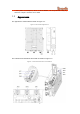
Lower power consumption, which reduces OPEX, can be powered easily by Baicells compact outdoor smart UPS 1.3 Appearance The appearance of Aurora243 is shown in Figure 1-1. Figure 1-1 Aurora243 Appearance The interfaces and indicators Aurora243 are shown in Figure 1-2.
The Aurora243 interfaces are described in Table 1-1. Table 1-1 Aurora243 Interface Description Interface Description PWR Power interface: The gNB supports DC power supply. DC: -40VDC to -57VDC, nominal -48VDC ETH RJ-45 interface, used for debug or data backhaul. OPT Optical interface, connect to external transmission network, used for data backhaul. GPS External GPS antenna, N-female connector. ANT0 External antenna 0, N-female connector. ANT1 External antenna 1, N-female connector.
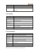
Item Description Channel Bandwidth N48: 10/20/30/40 MHz Multiplexing 2x2 MIMO (DL) Security Radio: SNOW 3G/AES-128 Backhaul: IPsec (X.509 AES-128, AES-256, SHA-128, SHA-256) 1.4.2 Interface Item Description Ethernet Interface 1 optical (SFP+) and 1 RJ-45 Ethernet interface (1 GE) Power Supply -40VDC to -57VDC, nominal -48VDC Protocols Used IPv4, UDP, TCP, ICMP, NTP, SSH, IPsec, TR-069, HTTP/HTTPs, DHCP Network Management IPv4, HTTP/HTTPs, TR-069, SSH, Embedded EPC VLAN/VxLAN 802.
1.4.4 Features Item Description Voice VoNR SON Self-Organizing Network Automatic Neighbor Relation (ANR) PCI confliction detection Traffic Offload Local breakout Maintenance Local/Remote Web maintenance Online status management Performance statistics Fault management Local/Remote software upgrade Logging Connectivity diagnosis Auto startup 1.4.5 Link Budget Item Description VSWR <= 1.5 Power Control UL Open-loop/Closed-loop Power Control, Allocation (3GPP TS 36.
Item Description Atmospheric Pressure 70 kPa to 106 kPa Power Consumption Maximum 150W Weight 18.7lbs / 8.5kg Dimensions (HxWxD) 13.1 x 9.4 x 4.3 inches 333 x 240 x 109 millimeters Installation Pole or wall mount 1.4.7 FCC Compliance This device complies with part 15 of the FCC Rules.
2. Installation Preparation 2.1 Support Materials In addition to industry standard tools, you will need the materials described in Table 2-1 during the installation. Table 2-1 Supporting Materials Item Power plug on the power side Figure Description None Prepare the power plug according to the actual installation site. The DC power supply is used, this is for two phase DC power plug. DC cord A DC power cable is provided with the device.
Item Figure Description The diameter of the pole is between 40mm to 100mm of hot-galvanized steel pipe Channel steel and equal angle steel installation are also supported. The width of the channel steel is 50mm to 100mm; the length of side of the angle steel is 63mm to 80mm. Pole Distribution box Cold shrink tube AC Air switch, socket, power grounding point, broadband access is all in the distribution box, which must be waterproofed.
multimeter 2.3 Construction Safety 1. The installation personnel must master the basic safe operation knowledge, through the training, and having the corresponding qualifications. 2. Before installation, the installation personnel must be prepared with safety protection, such as: safety helmet, safety belt, reflective clothing, gloves, and safety shoes, etc. 3. Before installation, the installation personnel must cross-check each other to ensure above preparations have done. 2.
3. Avoid to install near high-power wireless transmitter stations, such as radar stations, television stations, etc. If the gNB must be installed in such locations, you should check whether there is mutual interference, and take measures to prevent it. 4. Avoid to install on mountains. The mountain interference range is large, therefor the frequency reuse will be affected. Install gNB on high mountains in rural areas is often not good for the coverage of towns and villages in small basins. 5.
2.4.2 Environmental Requirements 错误!未找到引用源。 provides typical environmental specifications for this gNB. Table 2-2 Environmental Requirements Item Range Typical value Temperature -40°C to 55°C 25°C Relative humidity (no condensation) 0% to 100% 5% to 95% Safety voltage (DC) -40VDC to -57VDC -48VDC 2.5 Lightening & Grounding Protection You must protect the gNB, antenna, and GPS against lightning. Following are guidelines concerning grounding.
3. Installation 3.1 Unpacking Before opening the box, make sure the package is in good condition, undamaged and not wet. During the unpacking, avoid potential damaging impacts from hits or excessive force. Once unpacked, check whether the quantity is consistent with the packing list. 3.2 Installation Procedure Figure 3-1 provides an overview of the installation process. Figure 3-1 Installation Process 3.
Figure 3-2 GPS Installation Requirements No major blocking from buildings in the vicinity. Keep the rooftop buildings a distance away from the GPS. Make sure the space atop within 90 degrees (at least 45 degrees) is not blocked by any buildings. Avoid installing the GPS in the vicinity of any other transmitting and receiving devices, such as under the microwave antenna or high voltage cable. Avoid interference from other transmitting antennas to the GPS antennas.
3.4 Install on Pole Check to ensure the diameter of the pole is in the range of 1.6 inches to 3.9 inches (40mm to 100mm). The position of the gNB on the pole should be at least 47 inches (120cm) in height, as shown in Figure 3-4. Figure 3-4 Installation Height The mounting brackets include two components. The bracket mounting on the gNB side has been pre-assembled on the back of the device, as shown in Figure 3-5. The other component is used for pole mounting or wall mounting.
Figure 3-6 Pole Mounting Bracket Following will introduce how to fix the pre-assembled gNB on a pole. 1. Unscrew 4 screws on the assembled Pole bracket. Slide the two omega clamps to the left, and then turn them up or down. 2. Put the pole mounting bracket against the pole, turn the clamps to the horizontal position, and then slide the pole clamp to right, and finally re-tighten the four screws.
3. Align the two pins on the gNB bracket with the pin holes on the pole mounting bracket and vertically put the gNB from top to bottom until the hook on the gNB is stuck firmly into the corresponding slot on the pole mounting bracket. 4. Tighten the screws on the top of the bracket using a cross screwdriver. 5. The installation is complete, and proceed to “3.6 Connect Cable”. 3.5 Install on Wall Ensure that the wall can bear at least four times the weight of the gNB.
Figure 3-7 Wall Mounting Bracket Following will introduce how to fix the gNB on a wall. 1. Put the wall mounting bracket on the wall with the arrow pointing up and mark the drilling locations using a pencil or marker. 2. Drill two .4in/10mm diameter by 2.8in/70mm deep holes in the wall at the marked locations. 3. Insert expansion bolts, and then hang the wall mounting bracket on the expansion bolts, fasten with flat washers, spring washers and nuts.
4. Align the two pins on the gNB bracket with the pin holes on the wall mounting bracket and vertically put the gNB from top to bottom until the hook on the gNB is stuck firmly into the corresponding slot on the wall mounting bracket. Finally tighten the screws on the top of the bracket using a cross screwdriver. 5. The installation is complete, and proceed to “3.6 Connect Cable”. 3.6 Connect Cables 3.6.
An identification label should be attached after the cable is laid. Optical fiber laying requirements: Avoid circling and twisting during the laying. Avoid binding on a turn. Avoid pulling and weighing down the optical fiber. The redundant optical fiber must enwind the dedicated device. Grounding laying requirements: The grounding cable must connect to the grounding point. The grounding cable must be separate with the signal cables, of enough distance to avoid signal interference.
which may cause injury to the body of the construction personnel and the damage of RF power amplifier devices. 1. Take off dust caps of the ANT0 and ANT1 interfaces. 2. Pass one end of the RF cable through a cold shrink tube. 3. Connect RF cables to the ANT0 and ANT1 interfaces on the gNB, and tighten them with wrench. 4. Push the cold shrink tube to the top joint and pull out the strip. 5. Take out another cold shrink tube, and pass through the RF cable from the other end.
3.6.6 Connect Power Cable The power cable must meet the following requirements It is recommended to install an air switch in the distribution box for lightning protection and leakage protection, or a socket or plug with a fuse. The power cord needs to be protected by a hose sleeve or wiring tube. The distribution box should be grounding and have leakage protection. The length of the AC power cord and the DC power cord must be kept below 330 ft/100m.
ATTENTION: If the power adaptor is used, it must be connect to a surge arrester and grounding. It must be placed in a waterproof distribution box. 2. Assemble the power terminal on the gNB side. The gNB supports DC or AC power supply. The gNB provides power terminals based on the power supply mode selected by the customer.
3.6.7 Connect Ground Cable 3.6.7.1 Pole Grounding The purpose of the pole grounding is to protect the equipment in the station from the damage of lightning overvoltage as far as possible. However, the interfaces between the gNB and the outside world mainly include power system, grounding system, antenna feeder and lightning receiving device, and signal line.
requirements in the design, 300 × 40 × 4mm and fixed with expansion bolts. 5. The grounding wire must be made of the whole cable material, the intermediate joint is strictly prohibited, and the excess length should be cut. The skin shall be complete, and the insulation resistance of the core wire to the ground (or metal isolation layer) shall meet the technical requirements of the cable. 6. The grounding wire shall be connected to the integrated grounding bar of the building.
1. Unscrew one grounding screw, connect one end of the ground cable to the grounding screw, and fasten it again. 2. Repeat step 1 for the second grounding screw. 3. Once the gNB is installed at the outdoor location, the other end of the ground cable needs to connect to a good grounding point. 3.6.7.3 GPS Antenna Grounding If the length of GPS antenna is more than 5 meters, it is recommended to extend the installation distance.
3.7 Maintenance Chamber Waterproofing When all the installation has been completed, it is necessary to close the maintenance chamber of the equipment and play the role of waterproof at the same time. 1. Clamp the power cord to the wire position and seal the wire diameter 9 ± 1mm. 2. Put the pigtail / network cable on the wire, and seal the wire diameter 7 ± 1mm. 3.8 Power on to Check LED Status Power on the gNB, and wait a few minutes while the gNB boots up. Per the previous Table 1-2 in “1.
4. Attentions 4.1 1. FAQ After the device is connected with the power line, the PWR of the device will not be displayed when it is powered on. 1) Maybe the power line is not connected well, and the contact is poor. 2) There is no power in the circuit. 3) Poor contact of equipment power interface. 2. How to connect the antenna feeder 1) ANT0 is the main channel and ANT1 is the secondary channel. 3. GPS has been out of sync 1) The antenna is not installed in an open place.
4) Check whether the dip angle planning of the base station is reasonable. 5) Whether there is blocking in antenna coverage direct vision. 4.
Without the lightning rod Disordered wiring of distribution box Power line and signal cable are crossed Multiply the grounding point The RF feed system does not connect, the cell is activated and RF transmits signal 29