Baicells EG7035E-M11 User Manual V100R001C00 01 All rights reserved © Baicells Technologies Co., Ltd.
About This Document This document introduces the specifications of Baicells EG7035E-M11 CPE and guides users to install and configure it. Copyright Notice Baicells copyrights this specification. No part of this specification may be reproduced in any form or means, without the prior written consent of Baicells. Disclaimer This specification is preliminary and is subject to change at any time without notice. Baicells assumes no responsibility for any errors contained herein.
Contents 1. 2. 3. 4. Product Overview ....................................................................................................... 1 1.1 Introduction .......................................................................................................... 1 1.2 Features ................................................................................................................ 1 1.3 Appearance .........................................................................................
Appendix B Shipping List .............................................................................................
Figures Figure 1-1 EG7035E-M11 Appearance ........................................................................ 2 Figure 1-2 Interface and Button of EG7035E-M11 ....................................................... 2 Figure 1-3 LED Indicators of EG7035E-M11................................................................ 3 Figure 3-1 Install Ethernet Cable and USIM Card ....................................................... 8 Figure 3-2 Connection Diagram ...............................................
1. Product Overview 1.1 Introduction Baicells is a high-tech company dedicated in wireless broadband access solutions and service operation. With the advent of the Internet+ era, the development of WBB is imminent. Through continuous innovation, Baicells launches the world first mobile broadband system based on the Internet architecture and unlicensed spectrum. Baicells can provide series CPEs, include indoor and outdoor unit on different spectrums. Baicells EG7035E-M11 is a high performance outdoor CPE.
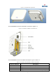
Figure 1-1 EG7035E-M11 Appearance The EG7035E-M11 interfaces and buttons are shown in Figure 1-2. Figure 1-2 Interface and Button of EG7035E-M11 The EG7035E-M11 interface and button description is given in Table 1-1. Table 1-1 Description of EG7035E-M11 Interface and Button Interface & Button Description PoE Connected to the PoE power adapter SD slot Support SD card USIM Slot Support 1.8V/3.
Interface & Button Description LED Indicator LTE signal strength Indicator& status indicator GND Connected to Earth by conductor The LED indicators are shown in Figure 1-3. Figure 1-3 LED Indicators of EG7035E-M11 The description of LED indicators are given in Table 1-2. Table 1-2 LED Indicator Description Identity Description MIU Color Yellow - LTE SIM LAN PWR Network state Indicator SIM card status indicator 100Mbps Eth Indication Power Indicator Status Description OFF Reserved.
Identity LTE Signal Description 5 LTEs, Indicate connection state and signal strength Color Green Status Description All OFF Signal is too weak to attach. Steady On According to signal strength in turn light up Blanking Scanning the LTE network The CPE is authenticating. CPE is getting IP address from the LTE network.
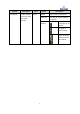
2. Technical Specifications 2.1 Basic Specification Table 2-1 Basic Specification Item Description LTE Standard 3GPP Release 9 Ethernet LAN Port One RJ-45 port 10/100 auto-sensing, auto-MDX, PoE LED Indicators Power/LET Signal/LAN Indicator USIM Support 1.8V/3V 2FF Restore Button Tact Button Long press over 10s to restore the factory settings Power Supply Input: Universal range 100V~240V AC Dimension About 248mm * 248mm * 80mm Weight About 1800g Color Pantone white C 2.
Item Description SIM PIN Management SIM Lock Network Connection setup Create, delete, and edit APNs Set up dial-up connection automatically Set up dial-up connection manual LTE Scan Mode Full Band Cell Lock Band / Frequency Preferred VPN Support VPN pass through Support PPTP tunnel mode NAT Port forwarding Port trigger DMZ UPnP Statistics LAN Link Status Transmit / Receive traffic Running Time 2.
Table 2-5 Environment Specification Item Operating Temperature Storage Temperature Operating Humidity Description -40℃ ~ 55℃ -40℃ ~ 70℃ 5% ~ 95% 7
3. Installation Guide 3.1 Support Materials Before installation, prepare the following support materials accordingly, as given in Table 3-1. Table 3-1 Support Materials for Installing Item Description Ethernet cable Outdoor Shield CAT5E Shorter than 330 feet Ground wire 16mm²yellow-green wire 3.2 Install USIM Card and Ethernet Cable 1. Screw the two screws on the waterproof cover. 2. Open the waterproof cover, and connect the Ethernet cable to the Ethernet interface. 3.
Figure 3-2 Connection Diagram 6. Power on, the LED indicator will light up. 3.3 1. Install on Pole Tighten the screws at the bottom of the bracket,as shown in Figure 3-3. Figure 3-3 Install the Bracket 2. Install the bracket on pole as shown as Figure 3-4.
Figure 3-4 Install on Pole 3.4 Install on Wall Install bracket on wall as show as Figure 3-5. Figure 3-5 Install on Wall 3.5 Grounding The EG7035E-M11 must be grounding, please contact professional person to operation.
Using grounding cable, connect the grounding screw to the ground row, as shown in Figure 3-6. Figure 3-6 Grounding 3.6 Regulatory Compliance FCC Compliance This device complies with part 15 of the FCC Rules. Operation is subject to the following two conditions: (1) This device may not cause harmful interference, and (2) this device must accept any interference received, including interference that may cause undesired operation.
Reorient or relocate the receiving antenna. Increase the separation between the equipment and receiver. Connect the equipment into an outlet on a circuit different from that to which the receiver is connected. Consult the dealer or an experienced radio/TV technician for help. Warning: This equipment complies with FCC radiation exposure limits set forth for an uncontrolled environment. This equipment should be installed and operated with minimum distance 50cm between the radiator & your body.
4. Configuration Guide 4.1 Log in The EG7035E-M11 manages, configures, and maintains the device by web management page. The steps to log in are as follows: 1. In the address column of browser, type in http://192.168.150.1, then press “Enter”, login in page is shown in Figure 4-1. Figure 4-1 Login Page 2. Enter the user name and password, click "LOGIN". After password authentication, you can log on to the web management page. The default user name and password is admin.
Figure 4-2 View Status 4.3 Basic Configuration 4.3.1 LTE Setting To set the LTE Network, perform the following steps: 1. Choose LTE. 2. In the LTE Setting area, configure the LTE network. 4.3.2 Set Connection Method To set the LTE network connection method, perform the following steps: 1. Choose “LTE>connection Method”, enter the setting connection method page, as shown in Figure 4-3.
2. In the connection Method area, set the connection method 3. There are two methods to connect the LTE network, it is needed to choose a method between Auto and Manual, if you want to auto connect to the LET network you should choose the Auto, otherwise you should choose Manual. 4. Click “SAVE & APPLY”. 4.3.3 Set Scan Mode To set the LTE network scan mode, perform the following steps: 1. Choose “LTE>Scan Method”, enter the setting scan method page, as shown in Figure 4-4. Figure 4-4 Set Scan Mode 2.
Figure 4-5 Lock Frequency 4. Click “SAVE & APPLY”. 4.3.5 Lock PCI To lock the PCI, perform the following steps: 1. Choose “LTE>Scan Method”. 2. In the LTE Scan Method area, click PCI Lock to lock the PCI. 3. Click ADD LIST you can choose a band, frequency and PCI, then click Add to add the frequency and PCI to the list, as shown in Figure 4-6.
Figure 4-6 Lock Frequency 4. Click “SAVE & APPLY”. 4.3.
Appendix A FAQs The POWER indicator does not turn on. Make sure that the power cable is connected properly and the CPE is powered on. Make sure that the power adapter is compatible with the CPE. Fails to Login to the web management page. Make sure that the CPE is started. Verify that the CPE is correctly connected to the computer through a network cable. If the problem persists, contact authorized local service suppliers. The CPE fails to search for the wireless network.
Appendix B Shipping List The product outward appearance, the color take the material object as, the picture only supply reference.
Caution: This device complies with Part 15 of the FCC rules and Industry Canada license‐exempt RSS standard(s). Operation is subject to the following two conditions: (1) this device may not cause harmful interference, and (2) this device must accept any interference received, including interference that may cause undesired operation. The manufacturer is not responsible for any radio or TV interference caused by unauthorized modifications or change to this equipment.