
Installation Manual
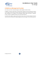
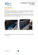
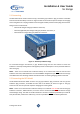
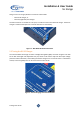
Table Of Contents

SL Range User Guide
Installation & User Guide
SL Range
8
5.1 Connecting
The BTLITH12110-SL model contains two (2) convenient grey Anderson plug connectors accessible
from the side of the battery as shown in Figure 3. Both can be used as input and outputs for charging
and running loads. Or one plug could be used to charge the battery and the second plug used for loads.
Charge sources could include:
- External AC charger with grey Anderson connector;
- External (regulated) solar charger with grey Anderson connector; or
- External DC-DC charger with grey Anderson connector.
Figure 3 – Dual Grey Anderson Plugs
For connected chargers and devices, a grey Anderson plug must be used. Check to ensure the
Anderson is correctly wired (positive and negative) and do not attempt to use any coloured Anderson
other than grey.
NOTE – There are no internal fuses inside the battery so an external fuse must be used for each
Anderson connector, 100A maximum. The internal BMS is designed for up to 100A continuous charge
and 100A continuous discharge. Please consider this when connecting charging devices and loads.
5.2 Connecting the DCS Model
The BTLITH12110-SL-DCS model contains one (1) grey Anderson plug connector and one (1) blue
Anderson plug connector, accessible from the side of the battery as shown in Figure 4. The grey
connector can used as input and output for charging and running loads.
NOTE – There are no internal fuses inside the battery so an external fuse must be used for the grey
Anderson connector, 100A maximum, to ensure never to exceed the BMS 100A continuous charge
and discharge rating. The cable to the blue Anderson connector should be protected by an external
fuse (at least 20A, rated for the cable size), as close as possible to the vehicle battery/alternator.