Installation and Configuration Manual 1
Important Notices SAFETY PRECAUTIONS FCC STATEMENT The Warnings, Cautions, and Notes contained in this manual have the following significance. WARNING Maintenance or operating procedures and techniques that may result in personal injury, illness, or death if not carefully followed. CAUTION Maintenance or operating procedures and techniques that may result in damage to equipment and/or minor to moderate personal injury if not carefully followed.
Important Water Safety Instructions When installing and using this Control System, basic safety precautions should always be followed, including those listed below: READ & FOLLOW ALL INSTRUCTIONS The effects of hyperthermia include: Unawareness of impending hazard. Failure to perceive heat. Failure to recognize the need to exit the spa. Physical inability to exit the spa. Unconsciousness resulting in a danger of drowning.
Important Electrical Safety Instructions When installing and using this Control System, basic safety precautions should always be followed, including those listed below: READ & FOLLOW ALL INSTRUCTIONS 1. DANGER - Risk of electric shock. Before making any electrical connections, make certain that the Main Power breaker from the house breaker box has been turned off. 2. DANGER - Risk of Electric Shock. Do not permit any electric appliance, such as a light, telephone, radio, or television within 5' (1.
Table of Contents This manual assumes that the Poolux Control System has been installed and configured according to this Installation Manual. Important Notices . . . . . . . . . . . . . . . . . . . . . . . . . . . . . . . . . . . . . . . . . . . . . . . . . . . . .2 Important Water Safety Instructions . . . . . . . . . . . . . . . . . . . . . . . . . . . . . . . . . . . . . . . . . .3 Important Electrical Safety Instructions . . . . . . . . . . . . . . . . . . . . . . . . . . . . . . . . . . . . . . . .
Table of Contents Connecting High Voltage Components To The System Control Center . . . . . . . . . . . . . . . . . . . . . . 28 General Requirements For High Voltage Equipment Wiring . . . . . . . . . . . . . . . . . . . . . . . . . . . . . 28 Pumps . . . . . . . . . . . . . . . . . . . . . . . . . . . . . . . . . . . . . . . . . . . . . . . . . . . . . . . . . 29 Underwater Lights . . . . . . . . . . . . . . . . . . . . . . . . . . . . . . . . . . . . . . . . . . . . . . . . . . .
Table of Contents Configuring The System: Step 1 - Training The First Wireless Panel . . . . . . . . . . . . . . . . . . . . . . 46 Configuring The System: Step 2 - Entering Configuration Mode . . . . . . . . . . . . . . . . . . . . . . . . . 47 Configuring The System: Adding A Device . . . . . . . . . . . . . . . . . . . . . . . . . . . . . . . . . . . . . 48 Configuring The System: Heater Control . . . . . . . . . . . . . . . . . . . . . . . . . . . . . . . . . . . . . . .
Diagrams Fig. 1 Poolux System Overview . . . . . . . . . . . . . . . . . . . . . . . . . . . . . . . . . . . . . . . . . . . . 10 Fig. 2 Pool/spa System . . . . . . . . . . . . . . . . . . . . . . . . . . . . . . . . . . . . . . . . . . . . . . . . . 13 Fig. 3 Pool/spa System with Pump Operated Pool Cleaner . . . . . . . . . . . . . . . . . . . . . . . . . . . . 14 Fig. 4 Pool/spa System with Pump Operated Cleaner, Solar, Jet Pump, Blower andPump-driven Water Feature. . . . . . . . . . . . . . . . . . . .
Diagrams Fig. 33 “S1” Switch and DIP Switches . . . . . . . . . . . . . . . . . . . . . . . . . . . . . . . . . . . . . . . . 47 Fig. 34 Acid Tank System. . . . . . . . . . . . . . . . . . . . . . . . . . . . . . . . . . . . . . . . . . . . . . . . 70 Fig. 35 Service Display Panel Button Functions--Quick Overview. . . . . . . . . . . . . . . . . . . . . . . . 73 Fig. 36 Service Display Panel, Pool Control . . . . . . . . . . . . . . . . . . . . . . . . . . . . . . . . . . . . .
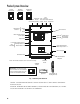
Poolux System Overview Insteon Transceiver Wireless Transceiver Dolphin RF Receiver Pool Expansion Com Monitor/ pH/ORP Boxes Ports Technician Wireless Conductivity (4 Max) (A,B,C) Panel Transceiver } Temperature Sensors Water Air Solar Service Panel } Filter Pressure Sensor Lights #1 Lights #2 3 Aux Inputs Dolphin RF 120V GFCIProtected Dimmable Low Voltage Heater Control } 24V Actuators Pool/Spa Suction & Return Valves 1-6 High Voltage Relays Filter Pump & Aux 1 - 7 GFCI for lights Chlorin
Poolux Specifications ELECTRICAL Power Requirements 120/240VAC, 50/60 HZ, 80 AMPS MAX Outputs 6 - Motorized Valve Actuators 24 VAC, 0.75A max 8 - 30 AMP Relays 2 - Dimmable Light Circuits - 120 VAC, 8.3A max (1000W) each, GFCI protected 1 - Fill Valve 24 VAC, 0.5A max (in place of valve actuator #6) 1 - Low Voltage Relay - (dry contact 24VAC; 1.
Package Content BEFORE INSTALLING THE POOLUX SYSTEM: • DETERMINE THAT YOU HAVE EVERYTHING NECESSARY TO COMPLETE THE INSTALLATION. • FIND A SUITABLE MOUNTING LOCATION FOR THE SYSTEM CONTROL CENTER, RECEIVERS AND PANELS. • PLAN AND DETERMINE WHERE COMPONENTS WILL BE PLUMBED. • PLAN WIRE RUNS AND WIRING CONNECTIONS.
Plumbing Schematic Suggestions NOTE: pH/ORP and Chlorine Generator board shown is optional POOL/SPA SYSTEM CONDUCTIVITY SENSOR LOCATION A B GND 9V A B 9V GND A TB4 J5 TB5 F1 9V 5V AIR J9 SOLAR J2 CHLORINE GENERATOR (OPTIONAL) ICSP ECOMATIC J10 V+ IN GRD PRESSURE AUX INPUTS TB2 CHLORINE GENERATOR CONTROL TB1 IN1+ IN1- J33 CAL AIR FILTER PRESSURE (OPTIONAL) 24VAC IN J32 FUSE 4A 250V WATER SOLAR B A B TB5 J1 WIRELESS TRANSCEIVER COM C TB5 TEMP SENSORS J8 POOL MON/
Plumbing Schematic Suggestions (cont’d) NOTE: pH/ORP and Chlorine Generator board shown is optional POOL/SPA SYSTEM WITH PUMP OPERATED POOL CLEANER CONDUCTIVITY SENSOR LOCATION A B GND 9V A B 9V A GND A B B TB5 TB5 9V 5V AIR J9 SOLAR J2 CHLORINE GENERATOR (OPTIONAL) ICSP ECOMATIC J10 V+ IN GRD PRESSURE AUX INPUTS TB2 CHLORINE GENERATOR CONTROL TB1 IN1+ IN1- J33 CAL AIR FILTER PRESSURE (OPTIONAL) TB4 J5 F1 J8 24VAC IN J32 FUSE 4A 250V WATER SOLAR WIRELESS TRANSCEIVER
NOTE: pH/ORP and Chlorine Generator board shown is optional POOL/SPA SYSTEM WITH PRESSURE CLEANER, SOLAR, JET PUMP, BLOWER & WATER FEATURE CONDUCTIVITY SENSOR LOCATION A B GND 9V A B 9V GND TB5 9V 5V AIR J9 SOLAR J2 CHLORINE GENERATOR (OPTIONAL) ICSP ECOMATIC J10 V+ IN GRD PRESSURE AUX INPUTS TB2 CHLORINE GENERATOR CONTROL TB1 IN1+ IN1- J33 CAL FILTER PRESSURE (OPTIONAL) TB4 J5 F1 J8 AIR SOLAR A TB5 J1 24VAC IN J32 FUSE 4A 250V WATER WATER WIRELESS TRANSCEIVER COM C
Plumbing Schematic Suggestions (cont’d) NOTE: pH/ORP and Chlorine Generator board shown is optional POOL/SPA SYSTEM WITH VALVE-CONTROLLED CLEANER CONDUCTIVITY SENSOR LOCATION A B GND 9V A B 9V TB5 9V 5V AIR J9 SOLAR J2 CHLORINE GENERATOR (OPTIONAL) ICSP ECOMATIC J10 V+ IN GRD PRESSURE AUX INPUTS TB2 CHLORINE GENERATOR CONTROL TB1 IN1+ IN1- J33 CAL FILTER PRESSURE (OPTIONAL) TB4 J5 F1 J8 AIR SOLAR GND TB5 J1 24VAC IN J32 FUSE 4A 250V WATER WATER WIRELESS TRANSCEIVER CO
NOTE: pH/ORP and Chlorine Generator board shown is optional POOL/SPA SYSTEM WITH PRESSURE CLEANER (VALVED), JET PUMP, BLOWER & WATER FEATURE CONDUCTIVITY SENSOR LOCATION A B GND 9V A B 9V TB5 9V 5V AIR J9 SOLAR J2 CHLORINE GENERATOR (OPTIONAL) ICSP ECOMATIC J10 V+ IN GRD PRESSURE AUX INPUTS TB2 CHLORINE GENERATOR CONTROL TB1 IN1+ IN1- J33 CAL FILTER PRESSURE (OPTIONAL) TB4 J5 F1 J8 AIR SOLAR GND TB5 J1 24VAC IN J32 FUSE 4A 250V WATER WATER WIRELESS TRANSCEIVER COM C
Plumbing Schematic Suggestions (cont’d) NOTE: pH/ORP and Chlorine Generator board shown is optional POOL/SPA SYSTEM WITH SOLAR CONDUCTIVITY SENSOR LOCATION A B 9V A B 9V GND A B GND A B TB4 J32 J5 TB5 TB5 F1 9V 5V AIR J9 SOLAR J2 CHLORINE GENERATOR (OPTIONAL) ICSP ECOMATIC J10 V+ IN GRD PRESSURE AUX INPUTS TB2 CHLORINE GENERATOR CONTROL TB1 IN1+ IN1- J33 CAL AIR SOLAR FILTER PRESSURE (OPTIONAL) 24VAC IN COM C FUSE 4A 250V WATER J8 WIRELESS TRANSCEIVER TB5 TEMP SENS
NOTE: pH/ORP and Chlorine Generator board shown is optional POOL ONLY SYSTEM OR SPA ONLY SYSTEM (NO BOOSTER) CONDUCTIVITY SENSOR LOCATION A B GND 9V A B 9V A FUSE 4A 250V B GND A 9V B TB4 J5 TB5 9V 5V AIR J9 SOLAR J2 CHLORINE GENERATOR (OPTIONAL) ICSP ECOMATIC J10 V+ IN GRD TB2 CHLORINE GENERATOR CONTROL TB1 IN1+ IN1- J33 PRESSURE AUX INPUTS IN2+ J12 IN2IN3+ RUN LT1 J13 LT2 J14 DOLPHIN RF S1 SETUP WHT J31 FROM GFCI LOAD IN3- S2 DIP SWITCH LIGHT 1 TB10 TB11
Plumbing Schematic Suggestions (cont’d) NOTE: pH/ORP and Chlorine Generator board shown is optional POOL ONLY SYSTEM WITH SOLAR, CLEANER PUMP AND WATER FEATURE PUMP CONDUCTIVITY SENSOR LOCATION A B GND 9V A B 9V GND A B 9V A FUSE 4A 250V B GND TB4 J5 TB5 9V 5V AIR J9 SOLAR J2 CHLORINE GENERATOR (OPTIONAL) ICSP ECOMATIC J10 V+ IN GRD PRESSURE AUX INPUTS TB2 CHLORINE GENERATOR CONTROL TB1 IN1+ IN1- J33 FILTER PRESSURE (OPTIONAL) 24VAC IN J32 F1 J8 AIR SOLAR WIRELESS TR
NOTE: pH/ORP and Chlorine Generator board shown is optional POOL ONLY SYSTEM WITH VALVE-OPERATED CLEANER & PUMP-DRIVEN WATER FEATURE CONDUCTIVITY SENSOR LOCATION A B GND 9V A B 9V A GND A B TB4 J5 FUSE 4A 250V TB5 F1 9V 5V AIR J9 SOLAR FILTER PRESSURE (OPTIONAL) 24VAC IN J32 J2 CHLORINE GENERATOR (OPTIONAL) ICSP ECOMATIC J10 V+ IN GRD PRESSURE AUX INPUTS TB2 CHLORINE GENERATOR CONTROL TB1 IN1+ IN1- J33 CAL AIR SOLAR WIRELESS TRANSCEIVER COM C TB5 TB5 J1 J8 POOL MON
Plumbing Schematic Suggestions (cont’d) NOTE: pH/ORP and Chlorine Generator board shown is optional SPA ONLY SYSTEM WITH JET PUMP, SPA BLOWER & PUMP-DRIVEN WATER FEATURE CONDUCTIVITY SENSOR LOCATION A 9V A GND B B 9V A GND A B TB4 J5 FUSE 4A 250V TB5 9V 5V AIR J9 SOLAR J2 CHLORINE GENERATOR (OPTIONAL) ICSP ECOMATIC J10 V+ IN GRD PRESSURE AUX INPUTS TB2 CHLORINE GENERATOR CONTROL TB1 IN1+ IN1- J33 CAL FILTER PRESSURE (OPTIONAL) 24VAC IN J32 F1 J8 AIR SOLAR WIRELESS TRAN
Mounting the System Control Center IMPORTANT: PLEASE READ THE FOLLOWING MOUNTING CONSIDERATIONS BEFORE INSTALLING THE SYSTEM CONTROL CENTER The System Control Center is contained in a rainproof enclosure. It is suitable for indoor or outdoor mounting. It should mount on a flat vertical wall and MUST be positioned so that the conduit knockouts are located at the bottom of the enclosure. Also it is important that it is not mounted in a confined space.
The Poolux Control System The System enclosure includes a number of features that are often considered optional like dimmable incandescent lighting. Other features like the fill valve are unique. The integration of the optional chlorine generation capablility rounds out the super-capable Poolux controller from Balboa.
MAIN CONTROLLER CIRCUIT BOARD COM B TB7 COM A TB6 COM C TB8 Pool Monitor/Technician Panel J32 Expansion Controller COM TB5 Wireless Transceiver J5 Conductivity Sensor 1 A B GND 1 TB5 24VAC IN TB4 1 9V A B 9V GND 24VAC IN COM C TB4 J32 1 J5 1 1 TB5 CAL TB5 WATER FUSE 4A 250V 1 WIRELESS TRANSCEIVER POOL MON/ TECH PANEL 1 COM A A GND J7 B A B 9V GND ANALOG C54 DIGITAL COND ORP PH 1 TB5 1 J8 9V 5V AIR J9 SOLAR J10 J2 ICSP 1 1 J33 TB2 TB1 On 1 System Control
System Control Center Wiring THE SYSTEM CONTROL CENTER IS A PERMANENTLY CONNECTED CONTROL. ROUTING OF THE WIRES The high voltage and low voltage wiring must be run separately, never sharing the same conduit or installed in the same compartment. The high voltage wires must be copper conductors sized for the required equipment current draw.
CIRCUIT BREAKER INSTALLATION CONTROL ELECTRONICS POWER CONNECTION The circuit breaker sub-panel has space for up to 8 single position or 4 double position circuit breakers. The installer is responsible for providing circuit breakers of appropriate ratings. See the table below for a list of the approved breakers that can be used. This information is also located on a label inside the enclosure door.
Connecting High Voltage Components to the System Control Center GENERAL REQUIREMENTS FOR HIGH VOLTAGE EQUIPMENT WIRING 1. Check to see that all equipment motors have built-in thermal protection before installing. 2. Pull appropriately sized wires for each piece of equipment from the equipment to the enclosure. 3. Each piece of equipment requiring high voltage should have its own high voltage relay.
Connecting High Voltage Components to the System Control Center (cont’d) PUMPS UNDERWATER LIGHTS Filter Pump Relay #1 is configured by default for use with a single-speed pump. While this function can be moved to another relay during system configurations, it is rarely practical to do so. The System Control Center has two (2 - 10AMP) onboard triac controlled outputs for underwater lighting as a standard feature. The light outputs can be individually programmed for either on/off or dimmable operation.
Connecting Low Voltage Components to the System Control Center IMPORTANT: Route all low voltage wiring through the cable slot on the bottom left side of the enclosure into the low voltage raceway. Never mix high voltage and low voltage wires/cables in the same conduit or compartment. VALVES VALVE ACTUATORS OPTIONAL FILL VALVE The System Control Center is capable of controlling six (6) 24VAC valve actuators. Run the valve actuator cable into the low voltage raceway.
Connecting Low Voltage Components to the System Control Center (cont’d) After all low voltage wiring has been installed, arrange the wiring so that it is somewhat evenly spaced along the length of the entry slot. Secure the wires by tightening the two screws. FIREMAN’S SWITCH CONNECTION FOR HEATER LOW VOLTAGE CONTROL CIRCUIT FOR HEATERS IN3+ This section applies to all heaters or heat pumps that have control circuitry of 24VAC or less.
Temperature Sensors The Pool System uses high quality 30K ohm thermistor type temperature sensors. Two sensors are provided (one for Air and one for Water). If this control is used with a solar heating system, an optional solar sensor must be purchased separately. WATER TEMPERATURE SENSOR INSTALLATION TO INSTALL THE WATER TEMPERATURE SENSOR ATTENTION: The water temperature sensor is 25’ long. Consider the sensor mounting locations BEFORE mounting the System Control Center.
WARNING: DO NOT USE 10K OHM SENSORS OR OTHER MANUFACTURER’S SENSORS WITH THIS CONTROL. INCORRECT TEMPERATURE READINGS WILL RESULT. AIR TEMPERATURE SENSOR INSTALLATION (IN THE SYTEM ENCLOSURE) 1. If the System Control is not installed in a building and is otherwise not influenced by direct sunlight, the temperature sensor can be mounted to the bottom of the enclosure. 2. In the low-voltage raceway, remove the knockout located next to the low-voltage cable slot, then install the Liquid-Tite connector. 3.
Locating and Installing the Spa-Side Control Panel LOCATION GUIDELINES: The Spa-side Control Panel is hereafter referred to as the “Panel", and should be carefully planned and installed during the initial pool/spa construction. This will allow for important steps to be completed before the concrete or gunite is placed. TO INSTALL SPA-SIDE CONTROL PANEL Planning Is Essential: The specific Panel location needs to be determined ahead of time and planned.
INSTALLATIONS THROUGH A VERTICAL WALL 3. Provide a 1" conduit. 4. Provide a 1" conduit through the concrete/gunite at the location selected for the Panel. The Panel will extend into the inside diameter of the conduit and the cable will be routed through it. Before concrete/gunite is placed, securely fasten the 1" conduit so that it will remain in position during the placement of the concrete/gunite.
Locating and Installing the Spa-Side Control Center (cont’d) 5. Cut the excess 1" conduit flush with the final finished surface. After all finish work has been completed (plaster, tile, coping stone, deck finished, etc.), cut the 1" conduit flush with the finished surface. Sawing the conduit will not produce a flush surface, so grind, sand, or file as necessary. After cutting flush, deburr the inside diameter of the conduit. 6. Pull the panel cable through the conduit.
Installing Spa-Side and Optional Dolphin Base Transceiver Modules GUIDELINES FOR INSTALLING THE RF MODULES 1. Position both receivers away from any cables (such as power lines, extension cords, cable lines, and phone lines). 2. Mount the RF Module far away from large metallic objects (such as fences, aluminum siding, metal piping, and rain gutters). 3. Be sure there are no metal objects between the transceiver and the wireless, in-home panel or between the receiver and the pool/spa (for Dolphin use). 4.
pH/ORP/Conductivity pH, ORP and Conductivity sensors are mandatory when a chlorine generator is being used. These reading will allow the control to generate chlorine, adjust pH, and deliver alerts when chemistry is out of the desired ranges. INSTALLATION OF SENSORS 1. Splice in one reducing tee for each sensor (pH, ORP and Conductivity) with pipe dimensions as required by existing pool plumbing. Sensors should be located after the filter and before the heater or electrolytic chlorine generator.
CALIBRATION AND CARE (CONT) Dislodging air from within the pH bulb tip Winterization During shipping or storage, the electrolyte within the sealed pH bulb tip may have been replaced by entrained air bubbles. This may cause erroneous readings. To dislodge the air and to force the electrolyte back into the pH bulb tip, grasp the electrode near the cable end (but not the cable itself), and swing it downwards through an arc. 1.
Optional Chlorine Generation Cell Installation In conjunction with the chemical sensors, the chlorine generator cell can help minimize the management and use of liquid or solid chlorine products.
Water Flow Connecting the cell cord to the cell In most cases (for 1.5” and 2” PVC) the total water flow can be directed through the Cell Housing as shown in Sketch 3a) without significantly affecting the flow rate and/or backpressure on the filter, etc. However, if flow rate is a concern (high horse-power pump, large diameter piping, etc.), the ‘Cell’ can be installed on a by-pass (as shown in Sketch 3b). Note the need for a valve to ensure a good flow of water through the cell. 1.
Expansion Controller Connection This section only includes instructions on connecting the Expansion Controller(s) to the System Control Center. A single installation may utilize up to four expansion boxes. INSTALLATION OF AN EXPANSION BOX 1. Install the Expansion Controller following the installation instructions that are included with it. 2. Run 4-conductor cable through the low-voltage raceway from the System Control Center to the Expansion Control Center.
DIP Switch Settings BEFORE Powering Up the System IDENTIFY THE DEFAULT CONFIGURATION THAT MOST CLOSELY MATCHES THE PLUMBING AND EQUIPMENT INSTALLED. DIP SWITCH SETTINGS Set The Dip Switch Settings On The Circuit Board As Shown. When looking at the DIP switches on the Service Panel, the ON position is to the right. 1. POOL/SPA COMBINATION 4. Filter Pump Heater 2 Separate Lights Auxiliary Filter Pump Heater Lights for Pool and Spa Auxiliary 2 Valve Actuators 2.
Start Up: Configuration Parameters Read over the Configuration Parameters to familiarize yourself with the configuration definitions and options for the Poolux System. DEFAULT SETTINGS AND CONFIGURATIONS DEFAULT SETTINGS CONFIGURATION PARAMETERS Filter Cycles All Disabled Chemistry pH ORP TDS 7.2 to 7.
Start Up: Configuration Parameters (cont’d) The configuration settings will automatically be set to operate according to a default specified by the DIP switch settings prior to Start Up. Settings other than Day/Time and Filter Settings do not need to be configured for operation but should be set for user preference. Configuration instructions for these items are not included in the Operation Manual.
Configuring the System: Step 1 - Training the First Wireless Panel The Main Menu Screen options shown may be displayed in a different order on your control and will only appear if available on your system. BASIC PANEL FUNCTIONS Mode-Pool Arrow Left Arrow Up Pool Temp Pool Light 7 LEDs correspond to the 7 items on the left side of the display . They light to indicate operation or alert.
Configuring the System: Step 2 - Entering Configuration Mode To Configure the System, move the SetUp-Run switch (S1) on the circuit board to the SetUp position. The system will enter configuration mode. (The first wireless panel must be trained prior to use. See previous page.) SYSTEM CONFIGURATION CONFIGURATIONMODE ENTERING Read page 45 regarding default configurations and DIP switch settings. Verify that the DIP switch settings reflect your equipment configuration.
Configuring the System: Adding a Device To add an auxiliary jet pump to the spa, go to the setup device screen in configuration mode (see page 43 on how to enter configuration mode). Once Setup is verified, a “Setup Devices” screen will appear. Scroll down to an unassigned “Aux Device”; right arrow to “Add Device.” ADDING A DEVICE Setup Devices ADDING A DEVICE AT-A-GLANCE Add Device Auxiliary 1 Mode Device Type Maximum Speed Output 1 Expansion Boxes Device No.
Configuring the System: Heater Control To configure a heater, choose Heater from the Setup Devices menu in Configuration Mode. Right Arrow to Add Device. This brings you to the Heater Configuration Screen. CONFIGURING A HEATER CONFIGURING A HEATER AT-A-GLANCE Setup Devices Heater Add Device Mode Device Type Maximum Speed Output 1 Expansion Boxes Device No. Output 2 Expansion Boxes Device No.
Configuring the System: Configuring a Solar Heater Solar heating can be added in conjunction with a gas heater or as a stand-alone heater. CONFIGURING A SOLAR HEATER CONFIGURING A HEATER AT-A-GLANCE Setup Devices Solar Valve Add Device Mode Device Type Maximum Speed Output 1 Expansion Boxes Device No. Output 2 Expansion Boxes Device No.
Configuring the System: Exiting Configuration Mode After Configuration is complete, left arrow to exit configuration and enter Automatic Mode. EXIT CONFIGURATION 1 2 Setup Devices Filter Pump Assigned Pool Light Assigned Spa Light Assigned No Heater Assigned Yes Cleaner Unassigned Pool Fill Unassigned Left Arrow from Setup Device Screen to Exit Configuration Mode. Want to exit? Arrow Down then Select to Exit.
System Information Your system information (accessories and settings) can be viewed within a few screens, beginning with the Check Configuration menu (Menu 4 below). The basic equipment installed is shown: 1) Pool and/or Spa, 2) Expansion Boxes, and 3) other features (menus 5 and 6). The menus may appear different depending on your accessories.
Setting Day and Time Day of the week and AM/PM settings cannot be set separately. Day of the Week changes automatically according to the date input, and the AM/PM setting is changed with the hour setting.
Setting Filter Cycles Filter Cycle settings are very configurable and can make use of multiple times during a given day, as well as different programming for different days.
SETTING FILTER CYCLES 8b 8a Filter 1 Setup All Days Weekends Weekdays Sunday Monday Tuesday Filter 1 Setup Enable On1 On On On OOn On On 1 Wednesday Thursday Friday Saturday You will be given a choice of weekly or daily options to set up your filters for operation. Left Arrow to Exit. (Filter 1 Setup Menu) 10 9 Filter 1 Setup Filter Mode Days to Run Timer 1 Start Timer 1 StopStop Pump Speed Enable Pool Filter Time 1 Start Enter Time 12: 00 AM 12:00 AM 12:00 AM High The hour will blink.
Heater Settings Actual operation of various heating devices can be configured using this menu.
Setting Display Preferences Configuration of the wireless panel LCD is controlled using these menus. DISPLAY SET UP DISPLAY SET UP AT-A-GLANCE Main Menu Display Setup Backlight (min) Sleep Time (min) Assign Display2 Key Tone LCD Contrast 1 2 Pool Temp Mode Pool Main Menu Device Control Scenes / Timer Heater Chemistry Mode Setup Pool Light Air Temp Spa Light Filter Pump 10/09/06 Pool Set 80F Monday 12:42 PM Alert / Error Heater 3 3b Setup Setup Dolphinay and Time Displaylphin Version Info.
Renaming Devices Devices can be renamed to personal preference. For instance, Aux Device 1 can easily be renamed “Waterfall” and will then be shown that way on the control. Names are stored in the main control system.
Assigning Panel LEDs The LEDs to the left of the display can be reassigned to devices that are considered most important for that particular control panel. This is helpful for monitoring the on/off state of these devices without reading the display.
Creating Scenes Scenes are used to assign one or more devices to a preset timer. For example, a scene named “Evening” could be created that turns on a pool or spa light, and an auxiliary device such as a waterfall at the same time each evening.
A scene can also be manually turned on or off. If multiple devices are assigned to a scene, they will turn on or off simultaneously when the scene is turned on or off.
Vacation Mode Vacation Mode is used to disable scene timers when going on vacation. Each scene has an option in its setup called “Run in Vacation.” If set to Yes, the scene timers will continue to operate even though Vacation Mode is turned on or off.
Chemistry High and Low Limits for each chemistry reading has been set by the manufacturer. If the chemistry sensor reading is outside the present limits, an alert will flash on the Main Menu Screen. Default limits can be changed to your preference. CHEMISTRY CHEMISTRY SETTINGS AT-A-GLANCE Main Menu Chemistry Set High ORP Set Low ORP Set High pH Enable Set Low pH Set High TDS Ecomatic Disable Set Low TDS ORP threshold Enable Chlorine Gen.
Device Timeout A Device Timeout is the length of time a device will run if turned on manually and not turned off.
Check Alerts CHECK ALERTS CHECK ALERTS AT-A-GLANCE Main Menu Check Alerts 1 Pool Temp Mode Pool Pool Light Air Temp Spa Light Filter Pump Heater 10/09/06 Pool Set 80F Monday 12:42 PM Alert / Error (Display Screen) 2a 2b Main Menu Main Menu Device Control Scenes / Timer Heater Chemistry Mode Setup Check Alerts Setup Setup Pool (Main Menu) 3 ! Alerts & Errors If there is no error, this pop-up screen will appear.
Spa-Side Panel Set Up You may choose the equipment that you would like to associate with the first two Spa Panel buttons. The Temp and Mode buttons cannot be reassigned. Choose the piece of equipment from the Device List, then press Select when the piece of equipment you desire is highlighted as illustrated below.
Optional Dolphin Remote Set Up You must designate the equipment that you would like the Jet and the Aux buttons to operate from the Dolphin Remote. Choose the piece of equipment from the Device List, then press Select when the piece of equipment you desire is highlighted as illustrated below.
Poolux Wireless Panel Cradle Installation Option The Wireless Panel comes with a charging cradle that can be installed on a wall inside the home for a convenient display while charging. Installing the cradle is not necessary to charge the panel; it can be charged independently from the cradle with the charge cord. INSTALLING THE WIRELESS PANEL CRADLE The cradle must be mounted in a location where it receives a strong signal at all times.
Faults A Fault is an indication of a serious error that can affect the operation of the pool system. One of the following messages will blink on the lower right side of the Wireless Pool Control display when a fault occurs. FAULT MESSAGES AND MEANINGS AIR SENSOR FAULT The Air Temperature Sensor has failed or has been disconnected. WATER SENSOR FAULT The Water Temperature Sensor has failed or has been disconnected. SOLAR SENSOR FAULT The rooftop temperature sensor has failed or has been disconnected.
Chemical Tank System Having a chemical tank provides a convenient way to dispense acid into your pool or spa to maintain the proper pH. A chemical tank system also reduces overall maintenance time for the owner, and optimizes the pool chemistry over time. INSTALLING THE ACID FEED TANK 3. If not already installed, install the bracket and slide the pump motor into the bracket from the top. Secure it with the hardware provided. Add the rain cover. 4.
INSTALLING THE ACID FEED LINES (CONT) 12. Once the filter is suspended at the proper height, route the outside tubing to the motor to determine how much is to be cut off when inserted into the suction (“In”) side of the motor. Note: the recessed “IN” and “OUT” ports for the tubes in the motor are approx 3/4” deep. Note: Do not install the tubing with tight radius bends, kinks, or without slack. 13. Using a sharp utility knife, cut the tubing square. If necessary, deburr the tube. 14.
The Service Panel Operation controls and displays for the Poolux and an optional chlorine generator are found on the Service Panel inside of the Poolux System Box. The Chlorine Generator control and display are located on the top portion of the panel, and the Poolux and display are located on the bottom portion of the panel.
POOLUX SERVICE CONTROL PANEL FEATURES Mode Button 1. “Automatic” Mode. 2. “Service Mode Device Control” shuts off all accessories until “Automatic Mode” is resumed. 3. “Service Time-out” shuts off accessories for the specified time limit shown, and “Automatic” Mode will resume automatically after the time has elapsed.
The Service Panel (cont’d) OPTIONAL CHLORINE GENERATOR CONTROL For detailed explanation and operation instructions, please refer to your ECOmatic Owner’s Guide. Cell Output: Factory preset and self-monitoring. Display will fluctuate around 100 when producing sanitizer unless in Winter Mode. System Control: Varies sanitizer production by turning cell on and off during filtration pump operation. Set at maximum for full production. Stand By: Unit is functioning normally and waiting to produce sanitizer.
Replacement Poolux Parts List COMPONENT . . . . . . . . . . . DESCRIPTION 40499 . . . . . . . . . . . . . . . . Actuator 24VA 53963 . . . . . . . . . . . . . . . . Panel Pool Display 54186 . . . . . . . . . . . . . . . . Dolphin II Pool 53770 . . . . . . . . . . . . . . . . Dolphin RF Receiver 71004 . . . . . . . . . . . . . . . . ECS24/36/48 Cell 71111 . . . . . . . . . . . . . . . . Replacement Cell Housing 23427 . . . . . . . . . . . . . . . . Kit Sensor, 10FT AIR POOLUX BAL 23428 . . . . . . . . . . .
balboa instruments, inc. 1382 bell avenue tustin, ca 92780 www.balboa-instruments.