Balboa's BP Troubleshooting & Service Manual THIS MANUAL COVERS THE FOLLOWING: SPA CONTROL SYSTEMS PANELS BP500 BP2000G1 TP900, TP800, TP600, TP400 42211B 60 Hz Manufactured under one or more of these patents. U.S. Patents: 5332944, 5361215, 5550753, 5559720, 5,883,459, 6253227, 6282370, 6590188, 6976052, 6965815, 7030343, 7,417, 834 b2, Canadian Patent: 2342614, Australian patent: 2373248 other patents both foreign and domestic applied for and pending. All material copyright of Balboa Water Group.
Introduction Intellectual Property Advisement Warnings: Danger! Risk of Electric Shock! All Intellectual property, as defined below, owned by or which is otherwise the property of Balboa Water Group or its respective suppliers relating to the Balboa Water Group BP500 Spa Control, including but not limited to, accessories, parts, or software relating there to (the “System”), is proprietary to Balboa Water Group and protected under federal laws, state laws, and international treaty provisions.
Codes and Compliance All of the electrical wiring methods and materials used to complete the electrical installation of the BP control systems must be in accordance with the National Electrical Code or the Canadian Electric Code, as well as any local electrical codes in effect at the time of installation. The selection of electrical materials required to accomplish this installation and the installation of the control system must be made by, or be under the direct supervision of, a qualified electrician.
Warning! Qualified Technician Required for Service and Installation Basic Installation and Configuration Guidelines Use minimum 6AWG copper conductors only. Torque field connections between 21 and 23 in lbs. Readily accessible disconnecting means to be provided at time of installation. Permanently connected. Connect only to a circuit protected by a Class A Ground Fault Circuit Interrupter (GFCI) or Residual Current Device (RCD) mounted at least 5’ (1.
Table of Contents Introduction . . . . . . . . . . . . . . . . . . . . . . . . . . . . . . . . . . . . . . . . 2 Intellectual Property Advisement . . . . End User Warning . . . . . . . . . . . GFCI . . . . . . . . . . . . . . . . . Warnings: Danger! Risk of Electric Shock! Codes and Compliance . . . . . . . . . . . . . . . . . . . . . . . . . . . . . . . . . . . . . . . . . . . . . . . . . . . . . . . . . . . . . . . . . . . . . . . . . . . . . . . . . . . . . . . . . . . . . . . . . . .
Testing Low Speed and High Speed at the AMP Pump Connector . . . . . . . . . . . . . . . . . . . 42 Testing the Sensor Set . . . . . . . . . . . . . . . . . . . . . . . . . . . . . . . . . . . . . . 43 Changing a System Circuit Board . . . . . . . . . . . . . . . . . . . . . . . . . . . . . . . . . 45 Component Failure and Replacement Testing . . . . . . . . . . . . . . . . . . . . . . . . . 46 Software Setups and Test Mode . . . . . . . . . . Setup Changes with DIP Switch 1 ON - BP500 . . . . .
Service Tools and Parts Checklist SERVICE TOOLS REQUIRED UÊ UÊ UÊ UÊ UÊ Ammeter (50A) with insulated clamps for probes Screwdrivers, assorted flat and Phillips Digital Multi-meter Padlock (to lock electrical disconnect during service) Pliers: Slip Joint & Needle nose UÊ UÊ UÊ UÊ Precision Thermometer - Digital Fever Type Silicone Tube Small Wire Cutters 3/8” and 1/4" Open End Wrenches (Heater wire nut removal) Logic Jumper, No.
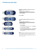
TP Panel Overview and User Guides TP900 System Models: BP2000G1 and other BP-Series Systems as required. Panel Model: TP900 Series, TP800 Series Software Version(s): Software versions vary and are constantly changing. See Tech Sheets for latest version and software compatibility. TP600 TP800 User Guide 40985 System Models: BP500 and other BP-Series Systems as required. Panel Model: TP600 Series, TP400 Series Software Version(s): Software versions vary and are constantly changing.
Product Identification All TP Panels have “Molex” Type Connectors On Every System, an Identification Label Is Placed on Top of the Casing Heater Element Specifications Are Shown on the Heater Tube Label On Every System, a Wiring Diagram Is Placed Inside the Door BP2000G1 – PN 56377-01 J43 TO J13 (BLOWER ON J14) IN SETUPS 3, 5, 9, 11, 12, 17, 18 J45 J79 J54 J77 J75 J78 J53 4 J18 115V J49 K5 3 2 J58 J44 J27 J23 SERIAL LOCATION J1 ON RT EXPANDER AUX DEVICE 2 SPD* PUMP 3 J15 LIGHT F4 3A SLO-B
General Troubleshooting & Servicing of Spa's Electrical Equipment HIGH VOLTAGE CAN SERIOUSLY INJURE OR KILL! ONLY EXPERIENCED TECHNICIANS SHOULD SERVICE THIS EQUIPMENT. DO NOT REMOVE THE PROTECTIVE COVERS FROM ANY ELECTRICAL ENCLOSURE, OR ATTEMPT TO SERVICE ANY RELATED ELECTRICAL DEVICE, UNLESS YOU ARE A QUALIFIED ELECTRICIAN OR SERVICE PROFESSIONAL. DANGER Risk of electric shock.
G.F.C.I. Troubleshooting Keep in mind that a majority of G.F.C.I. tripping problems can be attributed to incorrect wiring. G.F.C.I. troubleshooting usually finds the problem. IF CORRECT WIRING IS VERIFIED TO DISCONNECT THE HEATER UÊ Check to see if the proper G.F.C.I. is installed. UÊ Check the label in the system box near TB1 to determine the maximum amperage draw for the system. UÊ Be sure the G.F.C.I. is rated for more amperage than the system will draw. UÊ For a 240 V dedicated system, a 2-pole G.F.C.
0 Volt Residential Wiring Schematic with G.F.C.I. G.F.C.
Note: This applies to all Domestic BP Systems. A BP2000 System is shown for illustrative purposes. Bottom view of G.F.C.
240 Volt Residential Wiring Schematic with G.F.C.I. G.F.C.
Note: This applies to all Domestic BP Systems. A BP2000 System is shown for illustrative purposes. Bottom view of G.F.C.
Voltage Checks: Breaker Box, G.F.C.I. & System Box UÊ UÊ UÊ UÊ When checking for proper voltage, keep in mind that the acceptable voltage range is +/- 10% of the recommended voltage. Acceptable voltage when 120 V is specified is between 108 and 132 V. Acceptable voltage when 240 V is specified is between 216 and 264 V. Diagrams are on the following pages. VOLTAGE VERIFICATION - MOST G.F.C.I.
Wiring Checks WIRING CHECK PRECAUTIONS SYSTEM BOX WIRE GAUGE CHECK UÊ When working in a system box always be aware that it may contain high voltage. UÊ Always keep your fingers and hand tools away from any wiring or circuit board when the power is on. Touching anything in these areas can result in serious injury. UÊ All service calls, no matter how minor, should include a complete wiring check, beginning with the house breaker.
Testing a System with Power LOW VOLTAGE At Balboa, it’s been our experience that the majority of the problems associated with electronic control systems are due to low voltage. BROWN OUTS “Brown outs” can have an effect on the spa’s operation in a variety of ways. The control panel may go blank, have scrambled messages on the LCD, or only a few features will function.
Testing a System with Power (cont.) THESE READINGS SHOULD BE TAKEN UNDER PEAK LOAD CONDITIONS. IMPORTANT If the voltage is not in the acceptable range, call an electrician or the local electric company to diagnose the problem. TO DETERMINE THE CAUSE OF A BLOWN POWER INPUT FUSE Perform the following sequence of tests. Test the System UÊ Turn the power off. UÊ Be sure to replace the system power input fuse with the same type. UÊ Unplug the blower and all pumps.
Testing a System with Power (cont.) See manufacturer’s owners manual or reference card for general information on operating the spa, including programming filters and other settings that are changed from the topside control panel. SAFETY AND ELECTRICAL SYSTEMS PRELIMINARY PANEL CHECK UÊ Use minimum 6AWG copper conductors only. UÊ Torque field connections between 21 and 23 in-lbs. UÊ Connect only to a circuit protected by a Class A Ground Fault Circuit Interrupter (GFCI) CSA enclosure: Type 2.
Testing a System with Power (cont.) MOST PROBABLE OVERHEATING CAUSES, INSPECT THESE FIRST UÊ UÊ UÊ UÊ UÊ UÊ UÊ UÊ UÊ UÊ Check slice or ball valves. Make sure that they are open. Make sure the correct pump is installed. Clean the filter/skimmer if there is any blockage. Check heater element alignment. Check for debris on the heater element. In extremely hot weather, check for proper cabinet ventilation. Make sure the temperature sensor is fully inserted into the sensor fitting on the heater.
Manufactured under one or more of these patents. U.S. Patents: 5332944, 5361215, 5550753, 5559720, 5,883,459, 6253227, 6282370, 6590188, 6976052, 6965815, 7030343, 7,417, 834 b2, Canadian Patent: 2342614, Australian patent: 2373248 other patents both foreign and domestic applied for and pending. All material copyright of Balboa Water Group.
Acceptable Ranges for Testing Equipment VOLTAGE CHECKLIST ACCEPTABLE HEATER AMPERAGE DRAW RANGES All voltages specified as 120 V or 240 V, may show an acceptable variance of +/- 10%. Voltage Ranges Heater Type 120V Amp Draw 240V Amp Draw 5.5 kW @ 240 V 10.42 A - 12.74 A 20.83 A - 25.48 A 4 kW @ 240 V 7.58 A - 9.26 A 15.15 A -18.52 A 1 kW @ 120 V 7.58 A - 9.
BP 60Hz Spa Control System Wiring Diagrams Wiring Diagram - BP500, Part Number 56278, Setup No. 1 (as manufactured) Power Requirements: 240VAC, 60Hz, 40A, Class A GFCI-protected service (Circuit Breaker rating = 50A max.
GRN TB1 F6 30A 4 3 2 1 K2 J46 4 K4 J38 J60 J41 1 A/V HOT J53 J58 J11 J111 J10 J81 3 2 SENSOR A K5 K1 F3 0.3A SLO-BLOW J109 J43 J39 K9 F8 30A J33 CIRC PUMP F2 10A 250VAC J44 3 J48 J20 GND 5.
DEVICE VOLTS MAX AMPS 2-SP PUMP 1 240V 12A MAX AUX 240V 12A MAX AUX LINE 1 CONNECTION J19 SPA LIGHT 12V 1A CIRC PUMP 120V* 2A MAX OZONE 1A CIRC AND OZONE LINE 1 CONNECTION TV / AV 120V 3A HEATER 240V 5.
GRN TB1 F6 30A 4 3 2 1 K2 J46 4 K4 J38 J60 J41 1 A/V HOT J53 J58 J11 J111 J10 3 2 SENSOR A K5 K1 F3 0.3A SLO-BLOW J109 J43 J39 K9 F8 30A J33 CIRC PUMP F2 10A 250VAC K3 J44 3 J48 J20 GND 5.
DEVICE VOLTS MAX AMPS PUMP 1 240V 12A MAX AUX 240V 12A MAX AUX LINE 1 CONNECTION J19 SPA LIGHT 12V 1A CIRC PUMP 120V* 2A MAX OZONE 1A CIRC AND OZONE LINE 1 CONNECTION TV / AV 120V 3A HEATER 240V 5.
GRN TB1 4 3 2 1 K2 J46 PUMP 1 4 K4 J38 J60 J41 1 A/V HOT J53 J58 J11 J111 J10 J81 3 2 SENSOR A K5 K1 F3 0.3A SLO-BLOW J109 J43 J39 K9 F8 30A J33 F2 10A 250VAC K3 3 J48 J20 GND 5.
Manufactured under one or more of these patents. U.S. Patents: 5332944, 5361215, 5550753, 5559720, 5,883,459, 6253227, 6282370, 6590188, 6976052, 6965815, 7030343, 7,417, 834 b2, Canadian Patent: 2342614, Australian patent: 2373248 other patents both foreign and domestic applied for and pending. All material copyright of Balboa Water Group.
Troubleshooting Using Resistance - Ohm’s Law OHM’S LAW The direct current flowing in a conductor is directly proportional to the potential difference between its ends. It is usually formulated as V=IR, where V is the potential difference, or voltage, I is the current, and R is the resistance of the conductor. CONTINUITY 42211B Manufactured under one or more of these patents. U.S.
Testing a Fuse: Continuity THERE ARE NO SERVICEABLE PARTS ON THE PCB,. THE PREFERRED WAY TO CHECK FOR FUSE CONTINUITY IS WITH THE FUSES REMOVED FORM THE CIRCUIT. TESTING A FUSE: CHECK CONTINUITY WITH THE FUSE REMOVED A FUSE WITH THE METER READING “GOOD” A FUSE WITH THE METER READING “BAD” FUSES INSTALLED IN THE SYSTEM 0.3amp (part number 21581) 32 3amp (part number 20600) 10amp (part number 30122) 30amp (part number 30136) Manufactured under one or more of these patents. U.S.
Troubleshooting Heater Resistance TEST IS WITH POWER OFF TROUBLESHOOTING HEATER RESISTANCE Release tab Release tab Locate the heater connector. Disconnect the connector by depressing the tab. Pull the connector straight out. ACCEPTABLE HEATER OHM (Ω) RANGES Heater Type Ohms (Ω) 5.5 kW @ 240 V 9.42 Ω -11.52 Ω 4 kW @ 240 V 12.96 Ω -15.84 Ω 1 kW @ 120 V 12.96 Ω - 15.84 Ω **Note: 1 kΩ = 1000 Ω : kΩ may vary +/- 10% depending on the accuracy of the meter used.
Troubleshooting Heater Posts Resistance to Heater Housing TEST IS WITH POWER OFF TROUBLESHOOTING HEATER POSTS RESISTANCE TO HEATER HOUSING VERIFY THAT THERE IS NO HEATER “LEAKAGE” Release tab Release tab Locate the heater connector. Disconnect the connector by depressing the tab. Pull the connector straight out. Measure resistance from a heater post to the heater housing Verify there is NO continuity from the heater post to the ground/earth.
Troubleshooting with Voltage IMPORTANT! BEFORE TESTING A SPA CONTROL SYSTEM FOR VOLTAGE OR AMPERAGE, BE SURE OF THE FOLLOWING DANGERS: HIGH AND LOW VOLTAGE CAN KILL. QUALIFIED TECHNICIANS SHOULD BE PERFORMING THESE TESTS OR WHEN TESTING VOLTAGE WHEN TESTING AMPERAGE OBSERVE SAFETY AT ALL TIMES 42211B Manufactured under one or more of these patents. U.S.
Verifying Incoming Voltage at the Terminal Block - BP500, BP2000G1 CAUTION - TEST IS WITH POWER ON VERIFYING INCOMING VOLTAGE AT THE TERMINAL BLOCK (240V SYSTEM) BP2000 SHOWN (BP500 SYSTEM IS SIMILAR) Red to Black Wires = 240V White to Red Wires = 120V White to Black Wires = 120V 36 Manufactured under one or more of these patents. U.S.
Testing Pump Fuses for Damage with Voltage On - BP2000G1 CAUTION - TEST IS WITH POWER ON THERE ARE THREE 30A PUMP FUSES IN THE BP2000G1 SPA CONTROL SYSTEM. F6 AND F8 ARE ON THE MAIN BOARD. F1 IS LOCATED ON THE EXPANDER BOARD.
Testing Heater Voltage - All BP Systems CAUTION - TEST IS WITH POWER ON. AVOID TOUCHING THE HEATER ASSEMBLY WHILE PERFORMING THIS TEST. THE HEATER IS ATTACHED TO GROUND. Testing at the heater terminal verifies that there is not a broken line to the heater. It may also indicate problems that may not be apparent visually, such as corrosion or a damaged heater terminal post. However, before you do test, read on...
A Safer Way to Test Heater Voltages Equipment needed: UÊ Insulated clamps for your voltmeter probes Suggested attire: UÊ Safety glasses UÊ Rubber gloves (when measuring live electrical wires) 1. Turn the power OFF to the spa control system. 2. Set voltmeter for AC high voltage reading. Set clamps onto terminals securely. Be sure that both insulated boots fully cover the clamps.
Testing Pump Fuses for Damage with Voltage On - BP500 Due to the design of the BP500, the upper Logic board must be moved out of the way to test most of the power board fuses. To gain access to the power board: 1. Power down the system. 2. Remove the sensor wires from the logic board. Be sure to depress the release tab on the sensor connector. Do not pull on the wire. 3. Remove the four corner retaining screws. 4.
Testing Heater Amperage CAUTION - TEST IS WITH POWER ON PLACE CLAMP AROUND ONE HEATER WIRE, AND THEN THE OTHER WIRE. AMPERAGE HEATER TEST BP2000G1 AMPERAGE HEATER TEST BP500 ACCEPTABLE HEATER AMPERAGE DRAW RANGES 42211B Heater Type 120V Amp Draw 240V Amp Draw 5.5 kW @ 240 V 10.42 A - 12.74 A 20.83 A - 25.48 A 4 kW @ 240 V 7.58 A - 9.26 A 15.15 A -18.52 A 1 kW @ 120 V 7.58 A - 9.26 A - Manufactured under one or more of these patents. U.S.
Testing Low Speed and High Speed at the AMP Pump Connector TESTING LOW SPEED AND HIGH SPEED AT THE AMP CONNECTOR CAUTION - TEST IS WITH POWER ON Board Connector Key Ground Neutral (Common) Typically Line voltage for 2-speed pumps Typically Line voltage Note flat sides in connector WITH THE PUMP LOW SPEED ON, TAKE A VOLTAGE READING AT THE AMP RECEPTACLE ON THE PCB THIS WOULD TYPICALLY SHOW LOW SPEED VOLTAGE FOR PUMP ONE.
Testing the Sensor Set 1. Begin the diagnosis with the power off. Check sensor wires for cracks or damage that may indicate the presence of a rodent. 2. Inspect the connections of both sensors on the circuit board. The plugs must be clean. 3. If the sensors are not totally failing but are showing excessive (2° F/1.
Testing the Sensor Set (cont.) 7. If there is a message indicating an open or faulty sensor: UÊ Unplug the sensor set (but leave the original sensors in the heater) and plug in the test sensor set. Put both sensors into the same cup of warm water (ideally above the set temperature, so the spa won't try to heat during this test, as there is no heater protection during this test) and verify that they read the same temperature (within 1°F/0.5°C). UÊ If the problem is solved, replace the sensor set.
Changing a System Circuit Board HOW TO REPLACE A SYSTEM CIRCUIT BOARD IMPORTANT! BE SURE TO TURN THE POWER OFF BEFORE REPLACING ANY COMPONENT, ESPECIALLY A CIRCUIT BOARD. IMPORTANT! DO NOT REMOVE AND REPLACE THE CIRCUIT BOARD UNLESS THE FAULT HAS POSITIVELY BEEN DETERMINED TO BE THE CIRCUIT BOARD. HOW TO REMOVE A SYSTEM CIRCUIT BOARD NOTE: Before you begin, labeling all wires to be removed may help speed up reinstallation. The wiring diagram should always be used to ensure proper wire placement.
Component Failure and Replacement Testing - Software Setups and Test Mode All BP systems have the capability for Test Mode. Test Mode is used when changing setup configurations through the panel, which also means that wiring changes may be necessary. (See the specific spa control system Tech Sheet for more details.) Note: Although Test Mode allows access to certain utility features, most Utilities are available without entering Test Mode.
Setup Changes with DIP Switch 1 ON - BP500 Note: For complete variations of equipment configurations and setups, the latest Tech Sheet should be obtained on the system you're working on. The information for setup changes is included here in the event you have wiring diagrams available, and to facilitate a better understanding of how setup changes are made. READ AND UNDERSTAND THESE INSTRUCTIONS BEFORE BEGINNING THIS PROCESS.
Setup Changes with DIP Switch 1 ON - BP500 (cont.) Again, You will have 1 minute to complete the setup change after you manually exit Priming Mode. Immediately after exiting Priming Mode, press this sequence of buttons: Warm*, Light, Warm, Warm, Warm, Warm. Continue to press Warm until the display shows the Setup Number (S-01, S-02, etc.) you want to switch to. When the correct setup number is showing, press Light once, and the system will reset, using the newly-selected Setup from that point on.
Setup Changes with DIP Switch 1 ON - BP2500 Note: For complete variations of equipment configurations and setups, the latest Tech Sheet should be obtained on the system you're working on. The information for setup changes is included here in the event you have wiring diagrams available, and to facilitate a better understanding of how setup changes are made. TEST MENU ACCESS (S1, SWITCH 1 ON) SERVICE TECHNICIAN ONLY.
Removing the Heater Assembly from a BP Spa System Note: Be careful when removing a heater assembly from a spa plumbing system. Water may splash out under pressure. Water under pressure in the plumbing may splash out, and onto the system’s electronic board. Do not remove the system door until the water has been drained from the heater assembly housed in the system. 1. Turn off the main power. 2. Close off the slice valves (or, ball valves) adjacent to the heater assembly. 3.
TP800, TP900 Panel Operations - The Main Screen - Navigation SPA STATUS NAVIGATION Important information about spa operation can be seen quickly from the Main Screen. The most important features, including Set Temperature adjustment, can be accessed from this screen. Navigating the entire menu structure is done with the 5 buttons on the control panel. When a text item changes to white during navigation, that indicates the item is selected for action.
TP800, TP900 Priming Mode Start-up Sequence PREPARATION AND FILLING PRIMING THE PUMPS Fill the spa to its correct operating level. Be sure to open all valves and jets in the plumbing system before filling to allow as much air as possible to escape from the plumbing and the control system during the filling process. After turning the power on at the main power panel, the top-side panel will display a splash, or startup screen.
TP800, TP900 Spa Behavior BE SURE TO SET THE TIME-OF-DAY Setting the time-of-day is important for determining filtration times and other background features. “Set Time” will appear on the display if no time-of-day is set in the memory. On the Settings Screen, select the Time-of-Day line. On the Timeof-Day screen, simply navigate right and left to select the Hour, Minutes, AM/PM and 12/24 Hour segments. Use the Up and Down Buttons to make changes.
TP800, TP900 Adjusting Filtration CLEANUP CYCLE (OPTIONAL) When a pump or blower is turned on by a button press, a cleanup cycle begins 30 minutes after the pump or blower is turned off or times out. The pump and the ozone generator will run for 30 minutes or more, depending on the system. On some systems, you can change this setting. (See the Preferences section.
TP800, TP900 Panel Lock & Unlock RESTRICTING OPERATION (LOCKING THE PANEL) Lock Back Settings Panel Main Screen > Settings > Lock OFF OFF UÊ The control can be restricted to prevent unwanted use or temperature adjustments. UÊ Locking the Panel prevents the controller from being used, but all automatic functions are still active. UÊ Locking the Settings allows Jets and other features to be used, but the Set Temperature and other programmed settings cannot be adjusted.
TP800, TP900 Sensor and System Related Messages SYSTEM INFORMATION The System Information Menu displays various settings and identification of the particular system. As each item in the menu is highlighted, the detail for that item is displayed at the bottom of the screen. SOFTWARE ID: (SSID) Displays the software ID number for the System. System Information Back Software ID (SSID) System Model Current Setup Configuration Signature Heater Voltage Heater Type Software ID (SSID): M100_101 V0.
TP800, TP900 Sensor and System Related Messages (cont.) DRAIN MODE System Hold Main Screen > Settings > Hold > Drain Drain Off Some spas have a special feature that allows Pump 1 to be employed when draining the water. When available, this feature is a component of Hold mode.
TP800, TP900 Sensor and System Related Messages (cont.) THE GROUND FAULT CIRCUIT INTERRUPTER (GFCI) Settings Back Light Cycle Invert Panel Lock Hold Utilities Preferences Information Normal USED FOR VERIFYING A PROPER INSTALLATION Your spa may be equipped with a GFCI Protection feature. If your spa has this feature enabled by the manufacturer, the GFCI Trip Test must occur to allow proper spa function.
TP800, TP900 Sensor and System Related Messages (cont.) MOST MESSAGES AND ALERTS WILL APPEAR AT THE BOTTOM OF THE NORMALLY USED SCREENS. Several alerts and messages may be displayed in a sequence. Some messages can be reset from the panel. Messages that can be reset will appear with a “right arrow” at the end of the message. This message can be selected by navigating to it at pressing the Select button. COMMUNICATIONS ERROR The control panel is not receiving communication from the System.
TP800, TP900 Utilities Menu THE UTILITIES MENU CONTAINS THE FOLLOWING: PREFERENCES The Preferences Menu allows the user to change certain parameters based on personal preference. TEMP DISPLAY Change the temperature between Fahrenheit and Celsius. TIME DISPLAY Change the clock between 12 hr and 24 hr display. REMINDERS Turn the reminder messages (like “Clean Filter”) On or Off. CLEANUP Cleanup Cycle Duration is not always enabled, so it may not appear.
TP400, TP600 Standard Panel Operations - Main Screen - Navigation Note: TP400 menu structure is similar to the TP600. This section is only for quick reference as it applies to troubleshooting. For complete menu operations, please refer to BWG user guide, document No. 40940 or user guide 42185 for simplified menus. TP400/TP600 error codes and fault messages are similar to TP800/TP900. Navigation Navigating the entire menu structure is done with 2 or 3 buttons on the control panel.
TP400, TP600 Panel Utilities Menu If the system can power up, you have access to the Utilities and Fault Log menus.
TP400, TP600 Preparation and Priming PREPARATION AND FILLING Fill the spa to its correct operating level. Be sure to open all valves and jets in the plumbing system before filling to allow as much air as possible to escape from the plumbing and the control system during the filling process. ing for more than 2 minutes. Under NO circumstances should a pump be allowed to run without priming beyond the end of the 4-5 minute priming mode.
TP400, TP600 Message Codes The following are messages and features that can appear on the TP400 and TP600 panels. NOTE: LCD readouts may look slightly different than shown on screen.
TP400, TP600 Messages (cont.) A / B (A/B SENSOR TEMPERATURES) WATR TOO HOT -- -- -- -- When this is set to On, the temperature display will alternate to display temperature from Sensor A and Sensor B in the heater. Water is too Hot (OHS) – M029 FALT LOG (FAULT LOG) The Fault Log is a record of the last 24 faults that can be reviewed by a service tech. One of the water temp sensors has detected spa water temp 110°F (43.3°C) and spa functions are disabled.
A Reset Message May Appear with other Messages. MEM RSET -- -- -- -- Some errors may require power to be removed and restored. Memory Warning - Persistent Memory Reset* – M021 FLOW-RELATED CHECKS Check for low water level, suction flow restrictions, closed valves, trapped air, too many closed jets and pump prime. On some systems even when spa is shut down, some equipment may occasionally turn on to continue monitoring temperature or if freeze protection is needed.
TP400, TP600 Utilities Fault Log Menu THE FAULT LOG FAULT LOG MESSAGE CODES: TP400, TP600 The Fault Log stores up to 24 events in memory and they can be reviewed under the Fault Log Menu. The Fault Log is a record of the last 24 faults that can be reviewed by a service tech. UÊ UÊ UÊ UÊ UÊ UÊ Each event captures a Fault Message Code, how many days have passed since the fault, Time of the fault, Set Temperature during the fault, and Sensor A and B temperatures during the fault.
TP400, TP600 Utilities Menu - GFCI Test Feature Not Available on CE Rated Systems. A GFCI is an important safety device and is required equipment on a hot tub installation. Your spa may be equipped with a GFCI Protection feature. (UL rated systems only.) If your spa has this feature enabled by the manufacturer, the GFCI Trip Test must occur to allow proper spa function. Within 1 to 7 days after startup, the spa will trip the GFCI to test it. (The number of days is factory programmed.
TP400, TP600 Simplified vs. Standard Panel Operations SIMPLIFIED MENUS CHANGING MENUS THROUGH CONFIGURATIONS Simplified Menus is an option that manufacturers (OEM's) offer to their end users in order to provide an easier to navigate menu. A simplified menu structure does not have extended features such as Utilities, Restricting Operation, Unlocking, and so on; yet, provides basic spa operations that satisfy the needs of end users.
A Simplified Main Menu (Doc No. 42185B) Main Menus Navigation Navigating the entire menu structure is done with 2 or 3 buttons on the control panel. Some panels have separate WARM (Up) and COOL (Down) buttons, while others have a single Temperature button. In the navigation diagrams Temperature buttons are indicated by a single button icon. Panels that have two Temperature buttons (Warm and Cool) can use both of them to simplify navigation and programming where a single Temperature icon is shown.
Supplemental Information - Optional Balboa DolphinTM Remote THE DOLPHINTM REMOTE The Dolphin Remote works much the same way as your entertainment remote at home does; yet, it’s designed to control pumps, blowers, and any option that you have on your pool or spa--including entertainment equipment. HOW THE DOLPHIN WORKS The Dolphin communicates with a Dolphin RF Receiver (or IR Receiver). The receiver is wired into the Control System. 1.
Optional Balboa DolphinTM Remote (cont.) ASSIGNING A NEW ADDRESS TO THE DOLPHIN Preferences Back Temp Display Time Display Reminders Cleanup Dolphin Color Language F 12 HR On 0.5 HR 0 Blue English Dolphin Address Back 5 In some instances you may want to reset the address of your Dolphin. You’ll need to match that new address in the control system and that of your Dolphin.
Spa Guidelines to Keep in Mind Below are guidelines when designing replacing an older control system, or if designing a new spa system. This information is included in order to offer more insight into spa plumbing and mechanics. 1. The heater requires at least 20 Gallons per Minute (GPM) of flow for proper function. 2. Some systems may require at least 25 GPM. 3. The suction system for the 2-speed pump or for the circ pump must be dedicated.
Glossary CIRC PUMP (OR CIRCULATION PUMP) Low horse power pump designated especially for maintenance of filtration and heating. It often runs all day. CLEAN-UP (OR PURGE) CYCLE An action designed to circulate water to maintain sanitary conditions. Pumps or blowers purge standing water to prevent the water from becoming stagnant. FILTRATION CYCLE purpose of Priming Mode is to allow the user to run each pump and manually verify that the pumps are primed (air is purged) and water is flowing.
Index Symbols 1, DIP Switch 46 1, Switch 47 6AWG copper conductors 20 6-pin connector J40 71 30A pump fuses 37 120V Amp Draw 23, 41 120 V Draw 23 120V Watts 23 230V Amp Draw 23 230V Watts 23 240V Amp Draw 23, 41 240 V Draw 23 240V Watts 23 42012, Document No. 72 42013, Document No. 72 50211, Document No. 72 50212, Document No.
Index cycles, filtration 53 D damaged terminal 50 DEMO (Demo Mode) 64 Demo Mode 46, 57 Depress sensor tab 40 Depress tab 43 different, LCD readouts may look slightly 64, 65 DIP Switch 1 46 DIP switch positions of S1 64 disconnect, electrical 19 disconnect, local 19 Disconnect, Local 19 Document No. 42012 72 Document No. 42013 72 Document No. 50211 72 Document No.
Index immediately, GFCI should be reset 58 Information 55 information, Fault Log 46 Information, System 56 instructions, power connection 2 Interface, User 8 Invert 55 IR Receiver 71 isolate the logic board 40 Issues, System Related 16 L last 24 faults 46 latest version 8 Law, Ohm’s 31 LCD readouts may look slightly different 64, 65 LED, Flashing Heat 20 limits, amperage draw 19 Limit, Temp 46 Link the panel 47 Loads, Check Under Peak 16 Loads, Two Types of Peak 16 local disconnect 19 Local Disconnect 19 L
Index Priming Mode 65, 74 Problem 22 problem, blower 19 problem, board 44 problem, flow 21 problem, pump 19 problem, sensor 44 problem, suction 65 programmable circ pump 53 Programming 74 Programming Reference 8 properly reset the GFCI 58 Protection, Electrical 19 protection, freeze 53, 56 Protection, Freeze 65, 74 Pump, Circ 74 pump, circulation 74 pump problem 19 pump, programmable circ 53 Pumps, Troubleshooting 22 Pump Suction Blockage* 65 R Range, High Temperature 51 Range, Low Temperature 51 Ranges, Ac
Index Control 45 T tab, Depress 43 tab, Depress sensor 40 Table, Ohm 23 TB1 17 Tech Sheets 8 temperature, continue monitoring 56 temperature display will alternate 57 Temperatures, A/B Sensor 46 Temperature, Set 55 temperatures, sensor 21 Temp Limit 46 Temps, A/B 57 terminal connector 50 terminal, damaged 50 terminal, red TB1 18 test button 58 Test, GFCI Trip 58 Testing, Acceptable Ranges for 23 Test Menu 67 TEST Menu 46 Test Menu Access 46 test mode 20, 21 Test Mode 46, 47, 48, 59 Test Mode.
Index of Paragraph Topics 0.3amp (part number 21581) . . . . . . . . . . . . . . . . . 32 BP2600 Board . . . . . . . . . . . . . . . . . . . . . . . . . . 45 3amp (part number 20600) . . . . . . . . . . . . . . . . . 32 Brown Outs . . . . . . . . . . . . . . . . . . . . . . . . . . . 18 10amp (part number 30122) . . . . . . . . . . . . . . . . . 32 CE Product: . . . . . . . . . . . . . . . . . . . . . . . . . . . 58 30amp (part number 30136) . . . . . . . . . . . . . . . . .
Index of Paragraph Topics (cont.) Drain Mode . . . . . . . . . . . . . . . . . . . . . . . . . . . 57 Heater May be Dry (dr)* – M028 . . . . . . . . . . . . . . . . 65 Electrical Protection . . . . . . . . . . . . . . . . . . . . . . . 19 Heater Related Messages . . . . . . . . . . . . . . . . . . . 56 Exiting Priming Mode . . . . . . . . . . . . . . . . . . . . . . 52 Heater Start Up Information . . . . . . . . . . . . . . . . . . 20 Exiting Priming Mode . . . . . . . . . . . . . . . . . . . . . .
Index of Paragraph Topics (cont.) normally used screens. . . . . . . . . . . . . . . . . . . . . . 59 Pull the connector straight out. . . . . . . . . . . . . . . . . . 34 Most Probable Overheating Causes, Inspect These First . . . . 21 Pump 1 AMP cord . . . . . . . . . . . . . . . . . . . . . . . . 42 Motor Amperage Guidelines . . . . . . . . . . . . . . . . . . 23 Pumps . . . . . . . . . . . . . . . . . . . . . . . . . . . . . . 53 Navigation . . . . . . . . . . . . . . . . . . . . . . . . . . .
Index of Paragraph Topics (cont.) System Box Wire Gauge Check . . . . . . . . . . . . . . . . . 17 The water flow has failed* – M017 . . . . . . . . . . . . . . 56 System Information . . . . . . . . . . . . . . . . . . . . . . . 56 The water flow is low – M016 . . . . . . . . . . . . . . . . . 56 System Model . . . . . . . . . . . . . . . . . . . . . . . . . 56 The water is too hot – M029 . . . . . . . . . . . . . . . . . . 59 TB1 . . . . . . . . . . . . . . . . . . . . . . . . . . . . . . .
Index of Paragraph Topics (cont.) White to Red Wires = 120V . . . . . . . . . . . . . . . . . . . 36 Wiring Check Precautions . . . . . . . . . . . . . . . . . . . . 17 With the pump high speed ON, take a voltage reading at the AMP receptacle on the PCB . . . . . . . . . . . . . . . . . . . . . . 42 With the pump low speed ON, take a voltage reading at the AMP receptacle on the PCB . . . . . . . . . . . . . . . . . . . . . . 42 84 Manufactured under one or more of these patents. U.S.
Technical Notes 42211B Manufactured under one or more of these patents. U.S. Patents: 5332944, 5361215, 5550753, 5559720, 5,883,459, 6253227, 6282370, 6590188, 6976052, 6965815, 7030343, 7,417, 834 b2, Canadian Patent: 2342614, Australian patent: 2373248 other patents both foreign and domestic applied for and pending. All material copyright of Balboa Water Group.
Tustin Ca. 92780 (714) 384-0384 ©2013 Balboa Water Group. All rights reserved. 42211B April 22, 2012 Manufactured under one or more of these patents. U.S. Patents: 5332944, 5361215, 5550753, 5559720, 5,883,459, 6253227, 6282370, 6590188, 6976052, 6965815, 7030343, 7,417, 834 b2, 4/22/13 86 Canadian Patent: 2342614, Australian patent: 2373248 other patents both foreign and domestic applied for and pending. All material copyright of Balboa Water Group.