FILE NO.
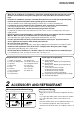
ADOPTION OF NEW REFRIGERANT This Air Conditioner is a new type which adopts a new refrigerant HFC (R410A) instead of the conventional refrigerant R22 in order to prevent destruction of the ozone layer. WARNING Cleaning of the air filter and other parts of the air filter involves dangerous work in high places, so be sure to have a service person do it. Do not attempt it yourself. The cleaning diagram for the air filter is there for the service person, and not for the customer. Service Manual Table FILE NO.
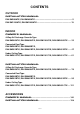
CONTENTS OUTDOOR INSTALLATION MANUAL RAV-SM560AT-E, RAV-SM800AT-E ....................................................................... 5 RAV-SM1100AT-E, RAV-SM1400AT-E ................................................................. 19 INDOOR OWNERS MANUAL 4-Way Air Discharge Cassette Type RAV-SM560UT-E, RAV-SM800UT-E, RAV-SM1100UT-E, RAV-SM1400UT-E ...... 33 Concealed Duct Type RAV-SM560BT-E, RAV-SM800BT-E, RAV-SM561BT-E, RAV-SM801BT-E, RAV-SM1101BT-E, RAV-SM1401BT-E ......
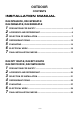
OUTDOOR CONTENTS INSTALLATION MANUAL RAV-SP560AT-E, RAV-SP800AT-E RAV-SM560AT-E, RAV-SM800AT-E 1 2 3 4 5 6 7 PRECAUTIONS FOR SAFETY .................................................................... 5 ACCESSORY AND REFRIGERANT ............................................................ 6 SELECTION OF INSTALLATION ................................................................. 7 REFRIGERANT PIPING ............................................................................. 12 EVACUATING ............
RAV-SP1100, 1400AT-E RAV-SM1100, 1400AT-E 1 PRECAUTIONS FOR SAFETY • • • • Ensure that all Local, National and International regulations are satisfied. Read this “PRECAUTIONS FOR SAFETY” carefully before Installation. The precautions described below include the important items regarding safety. Observe them without fail. After the installation work, perform a trial operation to check for any problem. Follow the Owner’s Manual to explain how to use and maintain the unit to the customer.
RAV-SP1100, 1400AT-E RAV-SM1100, 1400AT-E • When the air conditioner is installed in a small room, provide appropriate measures to ensure that the concentration of refrigerant leakage occur in the room does not exceed the critical level. • Install the air conditioner securely in a location where the base can sustain the weight adequately. • Perform the specified installation work to guard against an earthquake.
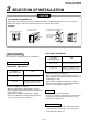
RAV-SP1100, 1400AT-E RAV-SM1100, 1400AT-E 3 SELECTION OF INSTALLATION CAUTION When using an air conditioner under low outside temperature condition (Outside temp.:–5°C or lower) with COOL mode, prepare a duct or wind shield so that it is not affected by the wind. upward/downward ( Discharge or leftward is also available.
RAV-SP1100, 1400AT-E RAV-SM1100, 1400AT-E Installation Place Necessary Space for Installation Obstacle at rear side 150 or more 1. Single unit installation 2. Obstacles at both right and left sides. 200 or more • A place which provides a specified space around the outdoor unit. • A place where the operation noise and discharged air are not given to your neighbors. • A place that is not exposed to a strong wind. • A place that does not block a passage.
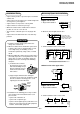
RAV-SP1100, 1400AT-E RAV-SM1100, 1400AT-E 3 SELECTION OF INSTALLATION • Before installation, check strength and horizontality of the base so that abnormal sound does not generate. • According to the following base diagram, fix the base firmly with the anchor bolts. (Anchor bolt, nut: M10 x 4 pairs) 1000 or more 1000 or more Installation of Outdoor Unit 150 600 150 400 365 Drain hole Open the upper side and both right and left sides.
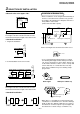
RAV-SP1100, 1400AT-E RAV-SM1100, 1400AT-E Optional Installation Parts (Local Procure) Knockout of Pipe Cover Parts name Q’ty A Refrigerant piping Liquid side : Ø9.5 mm Gas side : Ø15.9 mm B Pipe insulating material (polyethylene foam, 6 mm thick) C Putty, PVC tapes Each one 1 Rear direction Each one Pipe cover Side direction Front direction Refrigerant Piping Connection Down direction CAUTION TAKE NOTICE THESE IMPORTANT 4 POINTS BELOW FOR PIPING WORK Knockout procedure 1.
RAV-SP1100, 1400AT-E RAV-SM1100, 1400AT-E 3 SELECTION OF INSTALLATION In order to avoid the force applied to on the connecting section, be sure to fix the cables to the cord clamps provided on the pipe valve fixing plate and the electric parts box. How to remove the front panel 1. Remove screws of the front panel. 2. Pull the front panel downward. Front panel Electric parts box Removing the front panel, the electric parts appear at the front side. • The metal pipes are attachable to the piping holes.
RAV-SP1100, 1400AT-E RAV-SM1100, 1400AT-E 4 REFRIGERANT PIPING Tightening of Connecting Part REQUIREMENT (Unit: N•m) Outer dia. of copper pipe Tightening torque 6.4 mm (diam.) 14 to 18 (1.4 to 1.8 kgf•m) 9.5 mm (diam.) 33 to 42 (3.3 to 4.2 kgf•m) 12.7 mm (diam.) 50 to 62 (5.0 to 6.2 kgf•m) 15.9 mm (diam.) 68 to 82 (6.8 to 8.2 kgf•m) 1. Do not put the spanner on the cap. The valve may be broken. 2. If applying excessive torque, the nut may be broken according to some installation conditions.
RAV-SP1100, 1400AT-E RAV-SM1100, 1400AT-E 5 EVACUATING Air Purge This air conditioner can be installed up to the connecting pipe length and height difference in the following table. Height difference (m) Max.
RAV-SP1100, 1400AT-E RAV-SM1100, 1400AT-E Compound pressure gauge Handle position Pressure gauge –101kPa (–76cmHg) Handle Lo Charge hose (For R410A only) Service port (Valve core (Setting pin)) Manifold valve Handle Hi (Keep fully closed) Charge hose (For R410A only) Vacuum pump adapter for counter-flow prevention (For R410A only) Vacuum pump Packed valve at gas side How to open the valve Handle Closed completely Opened fully *1.
RAV-SP1100, 1400AT-E RAV-SM1100, 1400AT-E 6 ELECTRICAL WORK For the air conditioner that has no power cable, connect a power cable as mentioned below. Model Stripping length power cord and connecting cable SM1400AT-E SM1100AT-E SP1100AT-E SP1400AT-E RAV- 10 10 1 2 3 10 220 – 240 V Single phase 50 Hz Power supply Maximum running current 22.0 A Installation fuse rating 25 A (D type 40 22.8 A ) 50 40 Earth line Earth line H07 RN-F or 245 IEC 66 (2.
RAV-SP1100, 1400AT-E RAV-SM1100, 1400AT-E 7 FINAL INSTALLATION CHECKS Check and Test Operation For R410A, use the leak detector exclusively manufactured for HFC refrigerant (R410A, R134a, etc.). * The conventional leak detector for HCFC refrigerant (R22, etc.) cannot be used because its sensitivity for HFC refrigerant lowers to approx. 1/40. • Pressure of R410A is approx. 1.6 times higher than that of R22.
RAV-SP1100, 1400AT-E RAV-SM1100, 1400AT-E 7 FINAL INSTALLATION CHECKS Installation/Servicing Tools Changes in the product and components In the case of an air conditioner using R410A, in order to prevent any other refrigerant from being charged accidentally, service port diameter of the outdoor unit control valve (3 way valve) has been changed.
INDOOR CONTENTS INSTALLATION MANUAL 4-Way Air Discharge Cassette Type RAV-SP1100UT-E RAV-SM560UT-E, RAV-SM800UT-E, RAV-SM1100UT-E, RAV-SM1400UT-E 5 6 7 8 9 Accessory parts and Parts to be procured locally ........ 76 1 2 3 4 PRECAUTIONS FOR SAFETY ............................... 77 SELECTION OF INSTALLATION PLACE ............... 79 DRAIN PIPING WORK ............................................ 84 REFRIGERANT PIPING .......................................... 86 EVACUATING ..............................
RAV-SM560, 561, 800, 801BT-E RAV-SM1101, 1401BT-E Accessory parts and Parts to be procured locally r Accessory parts Part name Pipe insulator Q’ty Shape Part name 561BT 2 801BT 1101BT 1401BT 4 Shape 2 Clamp screw 561BT Clamp for air filter fixing Q’ty 2 (with pedestal) Connecting cable for High static pressure tap 801BT 1101BT 1401BT 4 Washer for unit hung-up 8 Installation Manual 1 Owner’s Manual 1 Part name Standard wired remote controller Q’ty Shape 1 r
RAV-SM560, 561, 800, 801BT-E RAV-SM1101, 1401BT-E 1 PRECAUTIONS FOR SAFETY • • • • Ensure that all Local, National and International regulations are satisfied. Read this “PRECAUTIONS FOR SAFETY” carefully before Installation. The precautions described below include the important items regarding safety. Observe them without fail. After the installation work, perform a trial operation to check for any problem. Follow the Owner’s Manual to explain how to use and maintain the unit to the customer.
RAV-SM560, 561, 800, 801BT-E RAV-SM1101, 1401BT-E • After unpacking the unit, examine it carefully if there are possible damage. • Do not install in a place that might increase the vibration of the unit. • To avoid personal injury (with sharp edges), be careful when handling parts. • Perform installation work properly according to the Installation Manual. Inappropriate installation may result in water leakage, electric shock or fire.
RAV-SM560, 561, 800, 801BT-E RAV-SM1101, 1401BT-E 2 SELECTION OF INSTALLATION PLACE WARNING • Install the air conditioner at enough strong place to withstand the weight of the unit. If the strength is not enough, the unit may fall down resulting in injury. • Install the air conditioner at a height 2.5m or more from the floor. If you insert your hands or others directly into the unit while the air conditioner operates, it is dangerous because you may contact with revolving fan or active electricity.
RAV-SM560, 561, 800, 801BT-E RAV-SM1101, 1401BT-E 3 INSTALLATION OF INDOOR UNIT WARNING Install the air conditioner certainly at a place to sufficiently withstand the weight. If the strength is insufficient, the unit may fall down resulting in human injury. Perform a specified installation work to guard against an earthquake. An incomplete installation can cause accidents by the units falling and dropping. Installation procedure 1.
RAV-SM560, 561, 800, 801BT-E RAV-SM1101, 1401BT-E 3 INSTALLATION OF INDOOR UNIT External view REQUIREMENT The hanging bolt pitch on horizontal direction (B) is not halved at center with the ceiling opening size. Therefore, check the relational position in the following figure.
RAV-SM560, 561, 800, 801BT-E RAV-SM1101, 1401BT-E 1. Hanging down of indoor unit Refer to installation figures of hanging material and hanging bolt. • Adjustment of hanging bolt length and nut position Adjust hanging bolt length and nut position as shown in the figure before hanging down the indoor unit. • Using the level vial, etc., set the horizontal level of the main unit within 5mm.
RAV-SM560, 561, 800, 801BT-E RAV-SM1101, 1401BT-E 3 INSTALLATION OF INDOOR UNIT Supply chamber Concealed duct type Channel Supply grille Supplying 200mm (diam.) round duct Supplying Indoor unit Returning Return air grille NOTE: • Recommended supplying grille size 400 cm² each or more Ledge ceiling concealed duct type Supplying Supply grille Indoor unit Supply chamber Supplying 200mm (diam.
RAV-SM560, 561, 800, 801BT-E RAV-SM1101, 1401BT-E 4 AIR DUCTING WORK Static pressure characteristics of each model Fig. 1 RAV-SM561BT (Round duct) Fig. 3 RAV-SM801BT (Round duct) Standard air volume 780m³/h 140 120 120 atic cp res Air volume limit (Min.
RAV-SM560, 561, 800, 801BT-E RAV-SM1101, 1401BT-E 4 AIR DUCTING WORK Fig. 5 RAV-SM1101BT (Round duct) Fig.
RAV-SM560, 561, 800, 801BT-E RAV-SM1101, 1401BT-E Installation reference (Example for RAV-SM801BT model) The air supply ducting work is classified in two ways, one is branched by the round ducts, and the other is branched by the square ducts. (Be sure to divide the air supply duct into three or more branches.) (Reference for square duct) When using the square duct, change the type of the air supply flange from round type to square flange at the local site.
RAV-SM560, 561, 800, 801BT-E RAV-SM1101, 1401BT-E 4 AIR DUCTING WORK Connecting method of the duct 1. Supply air side 1. Make the round duct according to inner dimension of the flange Use a glass wool board with inside/outside finishing 25mm-thickness and 24kg/m³-density. 2. Connect the flange and each type of duct. (Fig. 1) 1. Using 6 screws, mount the flange to the supply air port of the indoor unit. (Fig. 2) 2.
RAV-SM560, 561, 800, 801BT-E RAV-SM1101, 1401BT-E Hanging of indoor unit Nut Lift up the unit with a lifter, etc., and set the hanging metal in the hanging bolt. • Hook nut of the hanging bolt to the groove of the hanging metal on the main unit. • Using the level, etc., install the main unit horizontally. Failure to do this will cause water leakage Washer Hanging bracket Hanging bolt Mounting of filter and canvas for suction port 1.
RAV-SM560, 561, 800, 801BT-E RAV-SM1101, 1401BT-E 5 DRAIN PIPING WORK Piping material • For laying pipes underground, use hard vinyl chloride pipe. VP25 (Inner diamater Ø32mm) 1.5m to 2m Support bracket Indoor unit Thermal insulator Arched shape Piping and cautions • Set drain side of pipe at downward slope. (1/100 or more) • Be sure to apply thermal insulation (foaming polyethylene, 10mm-thickness or more) for pipes passing through the room.
RAV-SM560, 561, 800, 801BT-E RAV-SM1101, 1401BT-E If down-slope cannot be set on a drain pipe, drain-up is possible. • Set the height of drain pipe 550mm or less from the bottom face of the indoor unit. • Pull out the drain pipe from connecting port of the drain pipe of the indoor unit by 100mm or shorter, and stand up it vertically. • After standing up it vertically, arrange immediately so that it is set with down-slope.
RAV-SM560, 561, 800, 801BT-E RAV-SM1101, 1401BT-E 6 REFRIGERANT PIPING • Flaring dia meter size : A (Unit : mm) Refrigerant piping 1. If the outdoor units are to be mounted on a wall, make sure that the supporting platform is sufficiently strong. The platform should be designed and manufactured to maintain its strength over a long period of time, and sufficient consideration should be given to ensuring that the outdoor unit will not fall. 2. Use copper pipe with 0.8 mm or more thickness. 3.
RAV-SM560, 561, 800, 801BT-E RAV-SM1101, 1401BT-E 7 EVACUATING Open valve fully AIR PURGE Evacuate the air in the connecting pipes and in the indoor unit using vacuum pump. Do not use the refrigerant in the outdoor unit. For details, see the manual of vacuum pump. Open valves of the corresponding outdoor units fully.
RAV-SM560, 561, 800, 801BT-E RAV-SM1101, 1401BT-E 7 EVACUATING 801, 1101, 1401 type valve at gas side • As shown in the figure, be sure to use a double spanner to loosen or tighten the flare nut of the valve at gas side. If using a single spanner, the nut cannot be tightened with necessary tightening torque. On the contrary, use a single spanner to loosen or tighten the flare nut of the valve at liquid side. Cover Do not put the spanner or torque wrench, etc. on the cover.
RAV-SM560, 561, 800, 801BT-E RAV-SM1101, 1401BT-E 8 ELECTRICAL WORK NOTE: For selection and connection method of the power supply cords, refer to the details in the Installation Manual of the outdoor unit. CAUTIONS • Be sure connect earth wire. Do not connect the earth wire to gas pipe, pipe of water supply, lightning conductor, and earth wire of telephone. An incomplete grounding causes an electric shock. • If incorrect/incomplete wiring is carried out, it may cause an electrical fire or smoke.
RAV-SM560, 561, 800, 801BT-E RAV-SM1101, 1401BT-E 8 ELECTRICAL WORK Cabling Make a loop for the margin of the cable length so that the electric parts box can be taken out during servicing. 1. As shown in the figure, remove a screw and then remove cover of the electric part. 2. Strip wire ends (10 mm). 3. Match wire colors with terminal numbers on indoor and outdoor units’ terminal blocks and firmly screw wires to the corresponding terminals. 4. Connect the ground wires to the corresponding terminals.
RAV-SM560, 561, 800, 801BT-E RAV-SM1101, 1401BT-E 9 TEST RUN Before test run • Before turning on the power supply, carry out the following procedure. 1) Using 500V-megger, check 1MΩ or more exists between the terminal block 1 to 3 and the earth. If 1MΩ or less is detected, do not run the unit. Do not apply to the remote controller circuit. 2) Check the valve of the outdoor unit being opened fully. • To protect the compressor at activation time, leave power-ON for 12 hours or more be for operating.
RAV-SM560, 561, 800, 801BT-E RAV-SM1101, 1401BT-E 10 TROUBLESHOOTING Confirmation and check CODE No. When a trouble occurred in the air conditioner, the check code and the indoor unit No. appear on the display part of the remote controller. The check code is only displayed during the operation. If the display disappears, operate the air conditioner according to the following “Confirmation of error history” for confirmation. UNIT No. R.C. Check code No. Indoor unit No.
RAV-SM560, 561, 800, 801BT-E RAV-SM1101, 1401BT-E 11 APPLICABLE CONTROLS NOTIFICATION When using the equipment at the first time, it will take a lot of time that the remote controller accepts an operation after power was on. However, it is not a trouble. • Automatic address • While automatic addressing, the operation cannot be performed on the remote controller. • For automatic addressing, Max. 10 minutes (generally, approx. 5 minutes) are required.
RAV-SM560, 561, 800, 801BT-E RAV-SM1101, 1401BT-E 11 APPLICABLE CONTROLS • Select with shifting of the short plug on the indoor unit microcomputer P.C. board. Setup of external static pressure Matching with the resistance (External static pressure) of the duct to be connected, be sure to set up the tap exchange according to the basic operation procedure (1 → 2 → 3 → 4 → 5 → 6 ). • For the item code in Procedure 3, specify [5d].
RAV-SM560, 561, 800, 801BT-E RAV-SM1101, 1401BT-E Change of lighting time of filter sign Check and test operation According to the installation condition, the lighting time of the filter sign (Notification of filter cleaning) can be changed. Follow to the basic operation procedure (1 → 2 → 3 → 4 → 5 → 6 ). • For the item code in Procedure 3, specify [01]. • For the set data in Procedure 4, select the setup data of lighting time of filter sign to be changed from the table below.
RAV-SM560, 561, 800, 801BT-E RAV-SM1101, 1401BT-E 12 INSTALLATION/SERVICING TOOLS Tools Tools Applicable to R22 model Tools Gauge manifold o Flare tool (clutch type) Charge hose o Gauge for projection adjustment Electronic balance for refrigerant charging ¡ Torque wrench (nominal diam. 1/4, 3/8, 1/2, 5/8) o Applicable to R22 model ¡ — Vacuum pump adapter ¡ Gas leak detector o —— ¡ : Newly prepared (They are special requirements for R407C, separate from those for R22.
RAV-SM561, 801CT-E RAV-SM1101, 1401CT-E Accessory parts and Parts to be procured locally r Accessory parts Q’ty Shape Usage Owner’s Manual 1 — — Installation Manual 1 This manual — Part name Installation pattern 1 Thermal insulation pipe 2 Washer 4 Hose band 2 — Part name For holding down unit For connecting drain pipe Usage Shape Drain hose 1 For connecting drain pipe Bushing 1 For protection of edge at power taking-in port Thermal insulator 1 For thermal insulation of dr
RAV-SM561, 801CT-E RAV-SM1101, 1401CT-E 1 PRECAUTIONS FOR SAFETY • • • • Ensure that all Local, National and International regulations are satisfied. Read this “PRECAUTIONS FOR SAFETY” carefully before Installation. The precautions described below include the important items regarding safety. Observe them without fail. After the installation work, perform a trial operation to check for any problem. Follow the Owner’s Manual to explain how to use and maintain the unit to the customer.
RAV-SM561, 801CT-E RAV-SM1101, 1401CT-E • After unpacking the unit, examine it carefully if there are possible damage. • Do not install in a place that might increase the vibration of the unit. • To avoid personal injury (with sharp edges), be careful when handling parts. • Perform installation work properly according to the Installation Manual. Inappropriate installation may result in water leakage, electric shock or fire.
RAV-SM561, 801CT-E RAV-SM1101, 1401CT-E 2 SELECTION OF INSTALLATION PLACE WARNING • Install the air conditioner at enough strong place to withstand the weight of the unit. If the strength is not enough, the unit may fall down resulting in injury. • Perform a specified installation work to guard against an earth quake. An incomplete installation can cause accidents by the units failing and dropping. • Install the air conditioner at a height 2.5m or more from the floor.
RAV-SM561, 801CT-E RAV-SM1101, 1401CT-E Height of ceiling Before installation Set the installable height of the ceiling within 4m, otherwise the air distribution will become poor. If height of ceiling exceeds 3.5m, hot air becomes difficult to reach the floor surface, and then the change of setup of high ceiling is necessary. When incorporating a filter sold separately, the change of setup of high ceiling is also necessary.
RAV-SM561, 801CT-E RAV-SM1101, 1401CT-E 2 SELECTION OF INSTALLATION PLACE External view REQUIREMENT Strictly comply with the following rules to prevent damage of the indoor units and human injury. • Do not put a heavy article on the indoor unit. (Even units are packaged) • Carry in the indoor unit as it is packaged if possible. If carrying in the indoor unit unpacked by necessity, be sure to use buffering cloth, etc. to not damage the unit.
RAV-SM561, 801CT-E RAV-SM1101, 1401CT-E Installation of hanging bolts Pipe knockout hole • In case of taking pipe from the rear side Use M10 hanging bolts (4 pcs, to be local procure). Matching to the existing structure, set pitch according to size in the unit external view as shown below. * Cut off the groove section with a plastic cutter, etc. Rear cover New concrete slab 100 Install the bolts with insert brackets or anchor bolts.
RAV-SM561, 801CT-E RAV-SM1101, 1401CT-E 2 SELECTION OF INSTALLATION PLACE 2) Hang the unit to the hanging bolt as shown the figure below. Installation of indoor unit • Preparation before holding down main unit * Confirm the presence of the ceiling material beforehand because the fixing method of hanging metal when the ceiling material is set differs from that when the ceiling material is not set.
RAV-SM561, 801CT-E RAV-SM1101, 1401CT-E 3 DRAIN PIPING WORK Piping/Heat insulating material CAUTION • Following the Installation Manual, perform the drain piping work so that water is properly drained, and apply a heat insulation so as not to cause a dew. Inappropriate piping work may result in water leakage in the room and wet of furniture. Require the following materials for piping and heat insulating at site. Hard vinyl chloride pipe VP20 (Outer dia.
RAV-SM561, 801CT-E RAV-SM1101, 1401CT-E 3 DRAIN PIPING WORK Connection of drain hose Thermal insulating process • Insert the attached drain hose into the drain pipe connecting port on the drain pan up to the end. • Fit the attached hose band to the end of the pipe connecting port, and then tighten it securely. REQUIREMENT • Be sure to fix the drain hose with the attached hose band, and set the tightening position upward.
RAV-SM561, 801CT-E RAV-SM1101, 1401CT-E 4 REFRIGERANT PIPING AND EVACUATING • Flaring diam. meter size : A (Unit : mm) Refrigerant Piping A • The connecting sections of the refrigerant pipes are provided at the positions in the figure below. Rear side Upper side Right Outer diam. of copper pipe * When using the drain up kit sold separately, the pipe can be drawn out only from the upper side. +0 - 0.4 R410A R22 6.4 9.1 9.0 9.5 13.2 13.0 12.7 16.6 16.2 15.9 19.7 19.
RAV-SM561, 801CT-E RAV-SM1101, 1401CT-E 4 REFRIGERANT PIPING AND EVACUATING Piping with outdoor unit Open the valve fully • Shape of valve differs according to the outdoor unit. For details of installation, refer to the Installation Manual of the outdoor unit. Open the valve of the outdoor unit fully. A 4mmhexagonal wrench is required for opening the valve. For details, refer to the Installation Manual attached to the outdoor unit.
RAV-SM561, 801CT-E RAV-SM1101, 1401CT-E 5 ELECTRICAL WORK WARNING 1. Using the specified cables, ensure to connect the wires, and fix wires securely so that the external tension to the cables do not affect the connecting part of the terminals. Incomplete connection or fixation may cause a fire, etc. 2. Be sure to connect earth wire. (Grounding work) Do not connect the earth wire to gas pipe, city water pipe, lightning rod, or the earth wire of telephone. Incomplete grounding causes an electric shock.
RAV-SM561, 801CT-E RAV-SM1101, 1401CT-E 5 ELECTRICAL WORK Cable connection REQUIREMENT • • • • Be sure to connect the cables matching the terminal numbers. Incorrect connection causes a trouble. Be sure to pass the cables through the bushing of cabling connection port of the indoor unit. Keep a margin (Approx. 100mm) on a cable to hang down the electric parts box at servicing, etc. The low-voltage circuit is provided for the remote controller.
RAV-SM561, 801CT-E RAV-SM1101, 1401CT-E Cabling Remote Controller Cabling 1. Remove a screw and then remove cover of the electric parts box. 2. Strip wire ends (10 mm). 3. Match wire colors with terminal numbers on indoor and outdoor units’ terminal blocks and firmly screw wires to the corresponding terminals. 4. Connect the ground wires to the corresponding terminals. 5. Fix the cable with cord clamp. 6. Fix cover of the parts box and the terminal block surely with the fixing screws.
RAV-SM561, 801CT-E RAV-SM1101, 1401CT-E 6 TEST RUN Before test run • Before turning on the power supply, carry out the following procedure. 1) Using 500V-megger, check 1MΩ or more exists between the terminal block 1 to 3 and the earth. If 1MΩ or less is detected, do not run the unit. Do not apply to the remote controller circuit. 2) Check the valve of the outdoor unit being opened fully. • To protect the compressor at activation time, leave power-ON for 12 hours or more be for operating.
RAV-SM561, 801CT-E RAV-SM1101, 1401CT-E 7 TROUBLESHOOTING Confirmation and check CODE No. When a trouble occurred in the air conditioner, the check code and the indoor unit No. appear on the display part of the remote controller. The check code is only displayed during the operation. If the display disappears, operate the air conditioner according to the following “Confirmation of error history” for confirmation. UNIT No. R.C. Check code No. Indoor unit No.
RAV-SM561, 801CT-E RAV-SM1101, 1401CT-E 8 APPLICABLE CONTROLS NOTIFICATION When using the equipment at the first time, it will take a lot of time that the remote controller accepts an operation after power was on. However, it is not a trouble. • Automatic address • While automatic addressing, the operation cannot be performed on the remote controller. • For automatic addressing, Max. 10 minutes (generally, approx. 5 minutes) are required.
RAV-SM561, 801CT-E RAV-SM1101, 1401CT-E In case of installation to high ceiling When using wireless remote controller When the height of the ceiling to be installed exceeds 3.5m, adjustment of air volume is necessary. Set up the high ceiling. • Set according to the basic operation procedure (1 → 2 → 3 → 4 → 5 → 6 ). • Item code in Procedure specifies [5d]. • Select [Set data] in Procedure from “List of installable ceiling height” in this Manual. • For the item code in Procedure 3, specify [5d].
RAV-SM561, 801CT-E RAV-SM1101, 1401CT-E 8 APPLICABLE CONTROLS Change of lighting time of filter sign According to the installation condition, the lighting time of the filter sign (Notification of filter cleaning) can be changed. Follow to the basic operation procedure (1 → 2 → 3 → 4 → 5 → 6 ). • For the item code in Procedure 3, specify [01]. • For the set data in Procedure 4, select the setup data of lighting time of filter sign to be changed from the table below.
RAV-SM561, 801CT-E RAV-SM1101, 1401CT-E 9 INSTALLATION/SERVICING TOOLS Tools Tools Applicable to R22 model Applicable to R22 model Tools Gauge manifold o Flare tool (clutch type) Charge hose o Gauge for projection adjustment Electronic balance for refrigerant charging ¡ Torque wrench (nominal diam. 1/4, 3/8, 1/2, 5/8) o ¡ — Vacuum pump adapter ¡ Gas leak detector o —— ¡ : Newly prepared (They are special requirements for R407C, separate from those for R22.
RAV-SM561, 801CT-E RAV-SM1101, 1401CT-E 10 MAINTENANCE ○ Cleaning of air filter ○ ○ ○ ○ ○ ○ ○ ○ ○ ○ ○ ○ ○ ○ ○ ○ ○ ○ ○ ○ ○ ○ ○ ○ ○ ○ ○ ○ ○ 3 Soak up dust with a cleaner or clean with • [FILTER] is displayed on the remote controller, maintain the air filter. • Clogging of the air filter decreases the cooling/heating effect. wash. • If dust is heavy, wash it with tepid water including neutral detergent or water. CODE No.
ACCESSORIES CONTENTS OWNERS MANUAL WEEKLY TIMER FOR AIR CONDITIONER (SPLIT TYPE) RBC-EXW21E ............................................................................................................................ 144 REMOTE CONTROLLER FOR AIR CONDITIONER RBC-AS21E................................................................................................................................ 149 REMOTE CONTROLLER WIRELESS KIT RBC-AX22CE ..............
OWNERS MANUAL PRECAUTIONS FOR SAFETY WEEKLY TIMER FOR AIR CONDITIONER (SPLIT TYPE) WARNING WARNINGS ABOUT INSTALLATION RBC-EXW21E SuMoTuWeTh Fr Sa PROGRAM1 PROGRAM2 • Make sure to ask the qualified installation professional in electric work to install the weekly timer for air conditioner. If the weekly timer for air conditioner is inappropriate installed by yourself, it may cause water leak, electric shock, fire, and so on.
NAME AND OPERATION OF EACH PART HOW TO USE THE TIMER CORRECTLY 1. Operation procedure Program weekly timer set up SuMoTuWeTh Fr Sa PROGRAM1 Power ON ERROR PROGRAM2 PROGRAM3 1 2 3 4 WEEKLY TIMER DAY SET CANCEL HH MM CLEAR CHECK PROGRAM 8 6 5 7 2. Turn on the power supply of the air conditioner • Turn on the power supply of the air conditioner connected with a program weekly timer. (For cooling and heating, do not turn off the power supply for compressor heating.) 10,11 3.
3 4. Setup of the day of the week • Set the today of the week. (Example: Case of Wednesday) 1 SuMoTuWeTh Fr Sa PROGRAM1 While push button push DAY button to select “today” of the week. • While pushing SET button, each push button, the display of the present DAY day of the week flashes, and the display moves in order.
6. Set error 7. How to copy the program operation time If flashing ERROR is displayed when the program operation has been set up, correct the time following the procedure below. is displayed, ON time of the failed program flashes. 1. When flashing ERROR SuMoTuWeTh Fr Sa PROGRAM1 PROGRAM2 ERROR Push SET button to flash the time to be corrected. Using HH / MM buttons, correct ON/OFF time. Push SET button. When the setup is correctly performed, The correction has completed by pushing PROGRAM button. 1.
9. How to change the program operation time 1. Push button in the normal display status. 2. Select the required day reserve mark by pushing DAY button. 3. Push SET button. PROGRAM 12. Matters to be memorized button, the flashing 4. Each push part changes in the following figure. Put the indication on the time to be changed. 5. Using HH / MM buttons, change the time. 6. Push SET button. 7. Push PROGRAM button. Then the change operation has completed.
OWNERS MANUAL PRECAUTIONS FOR SAFETY REMOTE CONTROLLER FOR AIR CONDITIONER WARNING WARNINGS ABOUT INSTALLATION • Make sure to ask the qualified installation professional in electric work to install the remote controller. If the remote controller is inappropriate installed by yourself, it may cause, electric shock, fire, and so on. RBC-AS21E WARNINGS ABOUT OPERATION • When you are aware of something abnormal with the air conditioner (smells like something etc.
NAME AND OPERATION HOW TO OPERATE AIR CONDITIONER • For Cooling Only type, , and are not displayed on LCD. • Max. 8 indoor units can be operated by a remote controller. • Once setting the operation items, you can operate the previous condition by pushing button only. COOL/HEAT AUTO, HEAT, DRY, COOL, FAN 1 2 Power supply Turn on the power supply of the air conditioner 12 hours before starting the operation. Push 3 button.
OWNERS MANUAL Wireless Type PRECAUTIONS FOR SAFETY WARNING WARNINGS ABOUT INSTALLATION RBC-AX22CE • Make sure to ask the qualified installation professional in electric work to install the remote controller. If the remote controller is inappropriate installed by yourself, it may cause, electric shock, fire, and so on. WARNINGS ABOUT OPERATION • When you are aware of something abnormal with the air conditioner (smells like something etc.
NAME AND OPERATION • The signal receiving part is mounted to the ceiling panel. Signal Receiving Part Remote Controller • Max. 8 indoor units can be operated by a remote controller as a group. 1 3 4 2 5 3 12 ADR 5 7 4 13 6 – 152 – 8 ADR SET CL 9 10 SENSOR ACL S K N 14 15 16 17 6 7 8 Mode display section The operation mode is displayed. Start/Stop button Pushing this button starts, and pushing again stops the unit. Mode Select button Pushing this button selects an operation mode.
HOW TO SET THE FAN SPEED Operation Section Push each button to select a desired operation. • The details of the operation needs to be set up once, afterward, the air conditioner can be button only. used by pushing Display Section All indicators are shown in the right and the lower figures for the explanation. Only selected contents are display in actual operation.
HOW TO OPERATE THE UNIT HOW TO OPERATE THE TIMER • After setting of the timer, set the remote controller at a position where the signal can reach the sensors (indoor unit body) . (The signal of the timer operation is sent from the remote controller.) • Set up the timer during display of the operation mode. Cool/Heat AUTO, Heat, Dry, Cool, Fan Power supply Turn on the power of the wireless remote controller 12 hours before starting the operation.
HOW TO ADJUST AIR DIRECTION SLIDE SWITCH • Never move the flap (Air direction up/down adjusting plate) which is operated on the remote controller with hands except a case of cleaning of the flap. • While the unit stops, the flap (Air direction up/down adjusting plate) directs downward automatically. • During preparation of heating, the flap (Air direction up/down adjusting plate) directs upward. The swinging operation starts after heating preparation status has been cleared.
HOW TO HANDLE THE REMOTE CONTROLLER ADDRESS • Direct the transmitter of the remote controller toward the sensor (indoor unit body). When the signal is normally received, “Pi” sound is heard once. (“Pi, pi” sounds are heard only when the operation has started.) • The standard distance which the signal can be received is approx. 7m. The distance differs a little according to the capacity of the battery, etc.
HOW TO PERFORM TEMPORARY OPERATION BEFORE ASKING REPAIR WORK In the following cases, operate the air conditioner in emergency by emergency operation of the operation part (inside of panel or indoor unit). Before asking a repair work, check the follo wing items. • The battery in the remote controller expired. • A trouble occurred on the remote controller. • The remote controller have disappeared. Phenomenon Check again Operation does not start even if the switch is turned on.
INSTALLATION MANUAL Accessory parts Part Name Q’ty Remote controller Part Name Screw M4 x 25 How to install remote controller Q’ty Spacer 1 (200mm-cable attached) 2 Wire joint 2 Wood screw 2 2 Installation Manual To Personnel Charged in Installation (Electric) Work and Service NOTE 1 : Avoid to twist the remote controller cable with power supply cable, etc. or to store them in the same metal pipe, otherwise it causes a malfunction.
INSTALLATION MANUAL Accessory parts Part Name Q’ty Part Name Q’ty Spacer Remote controller 2 1 Wire joint 2 (200mm-cable attached) Clamper Screw M4 x 25 1 2 Installation Manual Wood screw 2 1 Requirement to install the remote controller Installation place – 159 – • Install the remote controller at a position within 1 to 1.5m from the floor, where the average temperature in the room can be felt.
INSTALLATION MANUAL Accessory parts Part Name Program weekly timer How to install the program weekly timer Q’ty 1 Connecting cable (Length: 1.2m) 1 Screws M4 x 25 2 Wood screws 2 Spacer 2 Owner’s Manual 1 Installation Manual Program Weekly Timer To Personnel Charged in Installation (Electric) Work and Service MODEL : RBC-EXW21E 1 NOTE 1 : Avoid to twist the program weekly timer cable with the power supply cable, etc.
TCB-TC21LE INSTALLATION MANUAL To Personnel Charged in Installation (Electric) Work and Service Accessory parts Part Name Q’ty Part Name Q’ty Spacer Remote sensor 2 1 (200mm-cable attached) Wire joint Small screw M4 x 25 2 2 Cable clamper Fix it with the spacer, but not so strongly. If the remote sensor does not fit closely to the wall, adjust it by cutting off the spacer. 3. Connect the remote sensor cable (2 cores) to the terminal numbers of the indoor unit.
INSTALLATION MANUAL Accessory parts No. Remote Controller Wireless Kit RBC-AX22CE Accessory Q’ty No. Accessory Q’ty 1 Sensor unit 1 4 Battery 2 2 Remote controller 1 5 Owner’s Manual 1 3 Remote controller holder 1 6 Truss tapping screw, 4 ×16 2 Installation of sensor unit 1. Open the suction grille, remove a screw, move the side panel toward you (direction of arrow), and then remove the side panel. (Fig. A) 2.
How to set the room temperature sensor How to perform cabling of sensor units Connection diagram Indoor unit Connection • Connect the cables out of the sensor unit to the terminal block for remote controller cabling of the indoor unit. (There is no polarity.) Sensor unit P.C. board Terminal block for remote controller cabling CN001 White Black 2P White • The room temperature sensors are equipped in the indoor unit and the wireless remote controller. One of two sensors works.
How to set up filter sold separately of the high ceiling Test run [S003] No.2 (Tap 1) and [S003] No.4 (Tap 2) are used. 1 2 3 4 • When the height of ceiling to be installed with a filter exceeds 3.5m or when installing a filter sold separately, tap-up of DC fan is required. Tap-up of DC fan can be set at No.2 (Tap 1) and No.4 (Tap 2) of DIP switch [S003] on the wireless sensor P.C. board. The wireless sensor P.C.
INSTALLATION MANUAL – 165 – Slid Screw Corner cap 3. The thermal insulation material is stuffed in the square hole provided to pass through cables of the panel, so take off it once and pass the cable out of the sensor of wireless remote controller through the grille. Using a clamp, fix the cable with screws and then be sure to stuff again the removed thermal insulation material as original. (Fig. 3) If the thermal insulation material is not stuffed, dewing may happen.
1. Preparation before installation of ceiling panel Ceiling Panel (1) Position check of indoor unit 1. Check the position of the indoor unit according to the Installation Manual. 2. Check the size of the ceiling opening hole, applied the following range. 860mm x 860mm to 910mm x 910mm 3. Using the installation gauge attached to the indoor packing, execute positioning of the ceiling surface and the indoor unit.
Square hole of indoor unit (3) Installation of ceiling panel The angle change of the flap is possible while the power supply is turned on. (Do not move forcibly the flap with hands. It may break the flap.) 1. For tentative hanging, insert the tentative hanging metal (stainless) inside of the ceiling panel into the square hole of the indoor unit. (Fig. 2) • The ceiling panel has directional ability against the indoor unit. Direct the mark of refrigerant pipe at the ceiling panel corner toward the pipe side.
INSTALLATION MANUAL Accessory parts and Parts to be procured locally DRAIN PUMP KIT FOR UNDER CEILING TYPE Accessory parts Part name TCB-DP22CE Q’ty Shape Part name Usage Drain up kit 1 — Drain up kit fixture 1 For mounting drain up kit Drain hose 1 For connecting vinyl chloride pipe of drain up kit Thermal insulating pipe 1 For thermal insulation of drain hose Installation Manual 1 This manual Be sure to hand to users.
1 PRECAUTIONS FOR SAFETY • • • • Ensure that all Local, National and International regulations are satisfied. Read this “PRECAUTIONS FOR SAFETY” carefully before Installation. The precautions described below include the important items regarding safety. Observe them without fail. After the installation work, perform a trial operation to check for any problem. Follow the Owner’s Manual to explain how to use and maintain the unit to the customer.
2 PREPARATION FOR INSTALLATION OF DRAIN UP KIT Cautions on installation INSTALLATION PROCEDURE OF DRAIN UP KIT Before installation • In the installation work of the drain up kit, the pipe cannot be draw out from other side than the upper side. • Apply thermal insulation for all the drain pipes. • Open two opening holes (Ø100, 2 positions) on the ceiling surface to be installed in order to pass refrigerant pipe and drain pipe. • Set a 450-square check port on the ceiling surface to be installed.
3 INSTALLATION PROCEDURE OF DRAIN-UP KIT Tightening connection Thermal insulating process CAUTION • Do not apply excessive torque. Otherwise, the nut may crack depending on the conditions. (Unit : N•m) Outer diam. of copper pipe Tightening torque 6.4 mm (diam.) 14 to 18 (1.4 to 1.8 kgf•m) 9.5 mm (diam.) 33 to 42 (3.3 to 4.2 kgf•m) 12.7 mm (diam.) 50 to 62 (5.0 to 6.2 kgf•m) 15.9 mm (diam.) 68 to 82 (6.8 to 8.2 kgf•m) Apply thermal insulation to pipes at liquid and gas sides separately.
4 Connection of drain hose at indoor unit side 1. Insert the drain hose attached to the indoor unit into the drain pipe connecting port of the indoor unit’s and into the drain pipe connecting port of the drain up kit’s drain pan. In this time, insert the drain hose until it strikes on the connecting port of the drain pipe. 2. Align the hose band attached to the indoor unit with the end of pipe connecting port, and then tighten it firmly. 3.
6 CABLE CONNECTION 1. Loosen the mounting screws (2 positions) of the cover of the electric parts box, and then remove the cover. 2. In the drain up kit, connect the connector (Blue 3P) for drain pump to P.C. board CN68 (Blue 3P) of the indoor unit, and the connector (Red 3P) for float switch to P.C. board CN34 (Red 3P) of the indoor unit respectively. In this time, remove 3P connector (Red 3P) for short-circuit of CN34 (Red 3P). CN68 (Blue 3P) Electric parts box 2 screws P.C.
How to install drain-up kit P.C. board 1. INSTALLATION MANUAL Installation of drain-up kit body (See Fig. 1.) Open the cover of drain-up kit body, align the position and fasten the body using the attached 4 tapping screws. 2. WARNING • Ask the qualified installation professional to install the drain up kit. If drain up kit is inappropriate installed by yourself, it may cause a water leak, an electric shock fire and so on.
Combination List of Adapter Parts INSTALLATION MANUAL Use for Indoor Unit Only MODEL : TCB-PCNT20E Network Adapter for Air Conditioner [For Installation Professionals] • • • • • Thank you for purchasing the parts sold separately for TOSHIBA package air conditioner. Before installation work, please read this manual thoroughly and install the products correctly. Ensure that all Local, National and International regulations are satisfied. Read this “CAUTION SAFETY” carefully before Installation.
In case of Concealed Duct (RAV-SM Installation Procedure • For installation of the adapter P.C. board and removal of the relay cable, be sure to wait for a while (approx. 1 minute) after turning off the power supplies of the air conditioner and the collective control remote controller. If not doing so, the adapter P.C. board may be damaged. In case of 4-way Ceiling Cassette (RAV-SM **0 UT-E) Procedure No. 1 Using the spacer (A) and (B), install the adapter P.C.
Address No. setup table (SW01) Setup of the Address No. To connect the indoor unit to the central remote controller using the adapter, it is necessary to set up the network address No. • It is required to agree the network address No. with the central remote controller system No. • The network address No. is set to 1 at the shipment from the factory. The following two methods are used for setup. 1.
To Customers Cautions in using the remote controller 1. After all the power supplies of the air conditioner have been turned on, turn on the power supply of the central remote controller. (16-systems : RBC-CR1-PE, 64-systems : RBC-CR64-PE) If the power supplies of the air conditioner and the remote controller are turned on at the same time, or if they are turned on in reverse order, the check code [97] may be temporarily displayed on the central remote controller.
INSTALLATION MANUAL 1 ELBOW PIPING KIT PRECAUTIONS FOR SAFETY • • • • Ensure that all Local, National and International regulations are satisfied. Read this “PRECAUTIONS FOR SAFETY” carefully before Installation. The precautions described below include the important items regarding safety. Observe them without fail. After the installation work, perform a trial operation to check for any problem. Follow the Owner’s Manual to explain how to use and maintain the unit to the customer.
2 • After unpacking the unit, examine it carefully if there are possible damage. • Do not install in a place that might increase the vibration of the unit. • To avoid personal injury (with sharp edges), be careful when handling parts. • Perform installation work properly according to the Installation Manual. Inappropriate installation may result in water leakage, electric shock or fire.
Specifications Deodorant filter Concealed Duct type Zeolite-3G Deodorant Filter Installation Manual Model: TCB-FPC11BE TCB-FPC21BE TCB-FPC31BE TCB-FPC41BE Model TCB-FPC11BE TCB-FPC21BE TCB-FPC31BE TCB-FPC41BE Conformed air conditioner model name — 561BT 801BT 1101 to 1401BT Quantity 1 1 2 2 Initial deodorant performance 70% Deodorant durable performance Approx. 12 months NOTES Installation of filter sold separately • Do not unpack the filter until you use it.
Installation of high-efficiency filter 1 Concealed Duct type High-Efficiency Filter 2 Installation Manual High-Efficiency filter (65%) Model: TCB-UFM11BE TCB-UFM21BE TCB-UFM31BE TCB-UFM41BE Model: TCB-UFH51BE TCB-UFH61BE TCB-UFH71BE TCB-UFH81BE High-Efficiency filter (90%) Install the air filter Be sure to fix the air filter with clamps in order to prevent falling. (Clamps are attached to the indoor unit.
Installation of filter sold separately 1 Concealed Duct type 2 Deodorant Filter, Ammonium Filter Deodorant Filter Installation Manual Model: TCB-DF11BE TCB-DF21BE TCB-DF31BE TCB-DF41BE Model: TCB-DF11BE-AM TCB-DF21BE-AM TCB-DF31BE-AM TCB-DF41BE-AM Ammonium Filter • Do not unpack the filter until you use it. (Otherwise, life of the deodorant filter or ammonium filter is shortened.) • Keep this Manual with Owner’s Manual of the indoor unit.
MEMO