Device Net Expansion Board (Baldor Binary Protocol) Catalog No.
Table of Contents Section 1 General Information . . . . . . . . . . . . . . . . . . . . . . . . . . . . . . . . . . . Introduction . . . . . . . . . . . . . . . . . . . . . . . . . . . . . . . . . . . . . . . . . Limited Warranty . . . . . . . . . . . . . . . . . . . . . . . . . . . . . . . . . . . . . Safety Notice . . . . . . . . . . . . . . . . . . . . . . . . . . . . . . . . . . . . . . . . Precautions . . . . . . . . . . . . . . . . . . . . . . . . . . . . . . . . . . . . . . .
ii Table of Contents
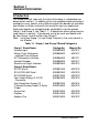
Section 1 General Information Introduction The Baldor controls represent the latest technology in microprocessor based motor controls. In addition to the user programmable parameters available in every control, many different expansion boards are available from Baldor to further customize the control to most any application. Expansion boards are categorized by compatibility into two groups: Group 1 and Group 2, see Table 1-1. A board from either group may be used alone in a control.
Limited Warranty For a period of two (2) years from the date of original purchase, BALDOR will repair or replace without charge controls and accessories which our examination proves to be defective in material or workmanship. This warranty is valid if the unit has not been tampered with by unauthorized persons, misused, abused, or improperly installed and has been used in accordance with the instructions and/or ratings supplied.
Safety Notice This equipment contains voltages that may be as great as 1000 volts! Electrical shock can cause serious or fatal injury. Only qualified personnel should attempt the start-up procedure or troubleshoot this equipment. This equipment may be connected to other machines that have rotating parts or parts that are driven by this equipment. Improper use can cause serious or fatal injury. Only qualified personnel should attempt the start-up procedure or troubleshoot this equipment.
WARNING: Be sure the system is properly grounded before applying power. Do not apply AC power before you ensure that all grounding instructions have been followed. Electrical shock can cause serious or fatal injury. WARNING: Do not remove cover for at least five (5) minutes after AC power is disconnected to allow capacitors to discharge. Dangerous voltages are present inside the equipment. Electrical shock can cause serious or fatal injury.
Section 2 Expansion Board Description Introduction The Device Net expansion board is a Device Net Group 2 Only Slave device using the predefined master/slave connection set, as defined by the ODVA. It is capable of explicit messaging, as well as polled and/or COS/Cyclic I/O. The interface is based on the Baldor Binary Protocol (BBP) command set. Group 2 board Device Net Communications Expansion Board Catalog No.
2-2 Description
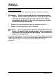
Section 3 Installation Board Installation This section describes the Expansion Board installation procedure. Caution: Before you proceed, be sure to read and become familiar with the safety precautions at the beginning of this manual. Do not proceed if you are unsure of the safety precautions described. If you have any questions, contact BALDOR before you proceed. 1. 2. Remove the expansion board from the shipping container. Remove all packing material from the board.
AC Controls (For all 15H Inverter, 21H Line Regen Inverter, 18H Vector, 22H Line Regen Vector and 23H Servo). Single Expansion Board Installation Procedure: 1. Be sure drive operation is terminated and secured. 2. Remove all power sources from the control. 3. Wait at least 5 minutes for internal capacitors to discharge. 4. Remove the four (4) Phillips head screws (1/4 turn) that secure the control cover. (For A & B size, remove four screws that secure the cover.
AC Controls Single Expansion Board Installation (Continued) Figure 3-1 Single Expansion Board Installation Expansion Board Motor Control Board Terminal tightening torque is 7 lb-in (0.8 Nm) maximum.
AC Controls (Continued) Dual Expansion Board Installation Procedure: 1. Be sure drive operation is terminated and secured. 2. Remove all power sources from the control. 3. Wait at least 5 minutes for internal capacitors to discharge. 4. Remove the four (4) Phillips head screws (1/4 turn) that secure the control cover. (For A & B size, remove four screws that secure the cover. On floor mounted G size enclosures, open the enclosure door). 5. Remove the control cover. 6.
AC Controls Dual Expansion Board Installation (Continued) 12. When complete, install the control cover using the four (4) Phillips head screws (1/4 turn). (For A & B size, install four screws that secure the cover. On floor mounted G size enclosures, close the enclosure door). 13. Restore all power sources to the control. 14. Restore drive operation.
3-6 Installation
Section 4 Hardware Setup DIP Switch Settings This procedure will configure the Device Net Expansion Board for communication with a computer or terminal. Reference Figure 4-1 and Table 4-1 for the following procedure. 1. Set DIP switches 1 and 2 for the desired baud rate. 2. Set switches 3 through 8 for the ID number desired. 3. Install the Device Net expansion board in the Series H control as instructed in Section 3 of this manual. Note: The switch settings can be changed after the board is powered up.
Figure 4-1 Board Configuration Device Net Expansion Board Catalog No. EXB013A01 PB1 Reset switch All switches shown in OFF position.
Table 4-1 Switch Settings Description 125kBPS 250kBPS 500kBPS MAC ID 0 MAC ID 1 MAC ID 2 MAC ID 3 MAC ID 4 MAC ID 5 MAC ID 6 MAC ID 7 MAC ID 8 MAC ID 9 MAC ID 10 MAC ID 11 MAC ID 12 MAC ID 13 MAC ID 14 MAC ID 15 MAC ID 16 MAC ID 17 MAC ID 18 MAC ID 19 MAC ID 20 MAC ID 21 MAC ID 22 MAC ID 23 MAC ID 24 MAC ID 25 MAC ID 26 MAC ID 27 MAC ID 28 MAC ID 29 MAC ID 30 MAC ID 31 MAC ID 32 ... MAC ID 63 1 OFF OFF ON ... 2 OFF ON OFF ...
LED Indicators Two LED’s are located on the Device net expansion board. MS - Module Status LED Displays the operational status of the Device Net Interface expansion board (EXB). Status is summarized in Table 4-2. Table 4-2 LED State OFF Green Flashing Green Red Flashing Red Flashing Red-Green Status Description No power is applied to the EXB. The EXB is operating in a normal condition. The EXB is in standby mode. The EXB may be attempting to communicate with the Series H control.
Control Terminal Strip Connections For Serial Mode operation, the Input/Output terminal strip of the control (J1 of the Vector and DC controls and J4 of the Inverters) is wired as shown in Figure 4-2. Connect the Enable, Forward Enable Switch, Reverse Enable Switch, External Trip and Opto Common connections as shown. Note: All opto-isolated outputs and analog outputs remain active while operating in the Serial Mode.
4-6 Hardware Setup
Section 5 Software Setup Configure Control Software for Device Net Mode The Series H control operating mode must be set to Serial to use the Device Net expansion board. There is no selection for Device Net on the Level 1 Input block Operating mode parameter list. However, selecting Serial with the Device Net expansion board installed will allow operation of the Device Net board.
Action Apply Power Press PROG key Press Y or B key Press Enter key Press Enter key Press Y or B key Press Enter key Press Y key Press Enter key Press Y or B key Press Enter key Description Display illuminates If no fault is found and control is programmed for local mode,OR, If no fault is found and control is programmed for remote mode Access programming mode. Scroll to Level 1 Input block Display Comments Logo is displayed for 5 seconds. STP MOTOR SPEED Display mode.
Action Press Y or B key Press ENTER key Press Y or B key Press ENTER key Press Enter key Press Y or B key Press ENTER key Press Y or B key Press DISP key Press LOCAL key Description Scroll to Level 2 blocks Display Comments PRESS ENTER FOR LEVEL 2 BLOCKS Select Level 2 blocks. PRESS ENTER FOR OUTPUT LIMITS Scroll to Communications block Select Level 2 Communications block.
Device Net Configuration The Device Net expansion board is a Device Net Group 2 Only Slave device using the predefined master/slave connection set, as defined by the ODVA. It is capable of explicit messaging, as well as polled and/or COS/Cyclic I/O. The interface is based on the Baldor Binary Protocol (BBP) command set. This EDS file (Electronic Data Sheets) is used by Device Net equipment to communicate with the BBP of the Baldor Device Net expansion board.
Table 5-1 Format of Input Assembly Instances # Byte Bit7 0 152 Bit5 Instance Byte Format Bit4 Bit3 Bit2 ControlState Warning T#4 T#27 CommandMode 1 151 Bit6 Output1 Output2 remote CtrlSourceT#3 2 SpeedActual T#18 (Low Byte) 3 SpeedActual T#18 (High Byte) 4 CurrentActual T#17 (Low Byte) 5 CurrentActual T#17 (High Byte) 0 SpeedActual T#18 (Low Byte) 1 SpeedActual T#18 (High Byte) 2 CurrentActual T#17 (Low Byte) 3 CurrentActual T#17 (High Byte) 4 ZeroSpd AtSpeed T#25 T#26
Table 5-1 Format of Input Assembly Instances Continued # Byte Bit7 0 Instance Byte Format Bit4 Bit3 Bit2 Warning Output1 Output2 T#4 network remote CtrlSourceT#3 T#5 Bit1 Output3 Bit0 Output4 TerminalStrip T#31 T#27 CommandMode 1 153 Bit6 Bit5 ControlState rev fwd RunCMDT#1 FreqActual T#19 (Low Byte) 2 3 4 CurrentActual T#17 (Low Byte) 5 CurrentActual T#17 (High Byte) 0 Input6 1 154 Input7 Input8 CommandMode T#5 Input9 Output1 TerminalStrip T#31 network Output2 Output3 Outp
Table 5-2 Format of Output Assembly Instances # Byte 0 Bit7 FaultRst T#46 1 101 102 2 3 4 5 0 1 2 3 4 5 6 FaultRst T#46 7 0 FaultRst T#46 1 103 2 3 4 5 0 1 104 2 3 4 5 6 7 FaultRst T#46 Instance Byte Format Bit5 Bit4 Bit3 Bit2 Bit1 Bit0 RunInhibit TableSelect Output1 Output2 Output3 Output4 T#2 T#39 T#75 CommandMode network remote rev fwd T#5 CtrlSourceT#3 RunCMDT#1 (RPM) SpeedRef T#7 (Low Byte) (RPM) SpeedRef T#7 (High Byte) TorqueRef T#9 (Low Byte) TorqueRef T#9 (High Byte) SpeedRef T#7 or
Notes: Used with CommandMode (T#5). These bytes represent the variables SpeedRef (T#7), or Position SpeedRef (T#13). Used with CommandMode (T#5). These bytes represent the variables TorqueRef or PositionRef. PositionRef requires 4 bytes. TorqueRef requires 2 bytes (Low Word). TableSelect is not implemented at this time. When a PLC updates memory in the middle of a double integer write of PositionRef, a problem may occur.
Section 6 Command Language Transaction Specification This section contains a detailed list of the transactions currently supported by the protocol. The list includes the transaction number, name, type description, and a detailed specification of the required and returned data. Note: Some transactions are not supported by all control types. Also some controls require variations in commanded data. Where these exceptions exist, they will be identified in the text.
Name The ‘Name’ field refers to a ‘C’ style variable for function names associated with the transaction. Use of these names is not necessary to interface with the transaction. These names may be used in present and future software drivers and libraries provided by Baldor. When used in conjunction with Baldor software tools, the transaction name is case sensitive. Type There are three basic transaction types: Set, Get, and those which do both: Set/Get.
Data Field The Data Field defines the data transfer requirements of the application layer message. This field describes the data using the ‘data type’ defined in Section 2.l. Commas separate individual elements of data. As previously discussed in Section 3, there are two types of application layer packets–. Command and Response. Command packets ALWAYS contain a transaction number (USINT). Response packets ALWAYS contain a transaction number (USINT) and a status (USINT).
Class The class field indicates the product classes that support the transaction. The product codes are as follows: E = Encoderless Vector I = Inverter S = Servo V = Vector V* = Vector with custom software for positioning Description The description field gives information regarding the use of the transaction. When possible the data range, scale, units, etc. are also given.
Transaction Specification Table Table 6-1 Transaction Specification Table T# 0 Name Null Type Set Data Field None Class All 1 RunCmd Set/ Get USINT All 2 RunInhibit Set/ Get BOOL All Description No action. This can be used to reset the watchdog timer, or as a placeholder in conjunction with a global Execute Buffer transaction. Network run / stop command. Get 0 = Stop (refer to stop mode parameter) 1 = Fwd 2 = Rev 3 = Bipolar Run * Actual motor direction is returned in Motor Direction.
Table 6-1 Transaction Specification Table Continued T# 3 Name CtrlSource Type Set Data Field USINT Class All 4 ControlState Get USINT E,V,S 5 CommandMode Set/ Get USINT All Description 0 = Keypad (local) 1 = Terminal strip (remote) 2 = Control from network 0 = Not Ready (no main power) 1 = Ready (disabled) 2 = Enabled 3 = Stopping 4 = Fault exists Command Mode 0 = None (Disabled) * 1 = Torque CMD selected source 2 = Torque CMD network 3 = Speed CMD selected source 4 = Speed CMD network 5 = Or
Table 6-1 Transaction Specification Table Continued T# 6 Name HzSpeedRef Type Set/ Get Data Field INT INT Class I, All 7 SpeedRef Set/ Get INT INT E,V,S, All 8 SpeedRefHigh Set/ Get DINT E,S,V 9 TorqueRef Set/ Get INT 12 PositionRef Set/ Get 13 PositionSpeed 15 Position V* Description Hertz Speed Reference. Set Units: 0.1 Hz (one decimal place) Speed reference Units: RPM (Standard Get Resolution) Speed reference (High Resolution) Units: 1/256 RPM .
Table 6-1 Transaction Specification Table Continued T# 17 Name CurrentActual Type Get Data Field INT 18 SpeedActual Get INT All 19 FrequencyActual Get INT E,I,S, V 20 PowerActual Get INT E,V,S 21 InputVoltage Get INT E,V,S Input line voltage Units: Volts RMS 22 OutputVoltage Get INT E,V,S Motor phase voltage (commanded) Units: Volts RMS 24 MotorDirection Get BOOL E,V,S 0 = Fwd 1 = Rev Actual in position feedback products, commanded in others.
Table 6-1 Transaction Specification Table Continued T# 28 Name AtPosition Type Get Data Field BOOL Class S,V Description 1 = At position 0 = Not at position 29 AtSetpoint Get BOOL E,V,S 1 = At setpoint 0 = Not at setpoint 30 AtSetSpeed Get BOOL E,V,S 1 = At set speed 0 = Not at set speed 31 TerminalStrip Get WORD All Digital I/O status word. Refer to Table 6-3 for description.
Table 6-1 Transaction Specification Table Continued T# 38 Name RunTime Type Get Data Field UDINT Class E,V,S Description Total time power has been applied. Units: seconds. 39 TableSelect Get/ Set USINT E,S,V 40 AccDecGroup Get/ Set USINT E,V,S Parameter table select Range 0 – 3 Note: DDC only supports 2 tables. Can only be changed when under network control Accel / decel group select Range 1 – 2 Can only be changed when under network control.
Table 6-1 Transaction Specification Table Continued T# 46 Name FaultRst Type Set Data Field BOOL Class All 47 FaultLog Get C: USINT FaultLogInde x R: UINT FaultCode, UDINT TimeStamp All 48 FaultCodeText Get C: USINT FaultCode R: STRING FaultText All 49 ForceFault Set BOOL All 50 SecurityStatus Get USINT All Description 1 = Execute fault reset 0 = No action Clears any active fault condition. Operation resumes at previous command.
Table 6-1 Transaction Specification Table Continued T# 51 Name SecurityLock Type Set Data Field INT or NONE Class All 52 CalcPresets Set BOOL E,S,V 56 BlockStructure Get USINT Level1Max, Level2Max, Level3Max, All Returns the number of blocks on each programming level. Assumes a max of three programming levels. 57 BlockDetail Get C: USINT Level, Block R: USINT MaxParams, STRING BlockName All Returns the number of parameters in the block and the BlockName (16 characters max.
Table 6-1 Transaction Specification Table Continued T# 58 Name BlockParamDetail Type Get Data Field 59 ParameterDetail Get C: INT Pnum, R: INT Pnum, Pvalue, Pmin, Pmax, Pdlft, Pprec, Ptype, STRING Pname, Punits All Returns full parameter detail information for the given Pnum. 60 ParameterList Get C: INT Pnum, ListIndex R: STRING ListText All Returns the enumerated list string for the given parameter number and list index. 16 characters max.
Table 6-1 Transaction Specification Table Continued T# 61 Name ParameterValue Type Set/ Get 62 BatchSend Get 63 BatchRcv 64 FactorySettings Data Field Class All Description Change / request value of specified user parameter. Returned value will give actual, after any bounds checking. Refer to the control manual for description. C: INT GroupNumbe r R: INT PnumN, PvalueN, ... N=16 All Set INT PnumN, PvalueN, ...
Table 6-1 Transaction Specification Table Continued T# 69 Name ClearAll Type Set Data Field USINT Class All Description Reserved for factory use. 70 LogClear Set USINT All Reserved for factory use. 71 AnalogInput1 Get UINT All AnalogInput2 Get UINT All Reads the raw value of the A/D converters on the control. Update rate and resolution vary per control. Unused MSBs will be padded with zero.
Table 6-1 Transaction Specification Table Continued T# 250 Name Type Data Field Class Description Reserved for future use. 251 Reserved for future use. 252 Reserved for future use. 253 Reserved for future use. 254 Reserved for future use. 255 Reserved for future use.
5 - Command Mode Command 5 USINT CommandMode Response 5 ST USINT CommandMode Type: Set/Get This transaction changes the command mode of the Series H control. The command mode is an 8–bit value. Loading the appropriate value into the command mode register activates the appropriate operating mode. Only one mode can be selected at a time. Table 6-2 provides a description of the possible command modes. Initial Condition: At powerup, the command mode is set to 00H (disabled).
Table 6-2 Command Mode Table Value Mode 0 None Class ALL Description No mode selected. Output stage of control remains off or disabled (voltage and current removed from the motor), regardless of RunCmd condition. Closes the current loop with command input from the source selected in the COMMAND SELECT parameter. 1 Torque CMD selected source S,V 2 Torque CMD Network S,V Closes the current loop with command input from the TorqueRef register.
31- TerminalStrip Command 31 Response 31 ST WORD TerminalStrip Type: Get This transaction returns a bit–wise word representing the status of the control digital inputs and outputs. Table 6-3 provides a description of the codes. Note: A bit value of 1=closed or ON, 0=open or OFF.
36 or 37 - Optionald# Command 36 Response 36 ST USINT Optionld Type: Get This transaction returns the id number for the option installed in the specified location. Table 6-4 provides a description of the possible values. Table 6-4 Optionald# Table ID 1 2 3 4 5 EXB No.
41 - WatchdogTime Command 41 UINT WatchdogTime Response 41 ST UINT WatchdogTime Type: Set/Get This transaction is used to change the value of the network watchdog timer. The value is entered in milliseconds (mS). The watchdog timer is used to detect a communications loss. When the time between network commands exceeds the value stored in this register, a fault is generated and the control is disabled. Each time a network command is received, the internal timer is reset to zero.
Table 6-5 ParameterDetails Table Field Name INT Pmin INT Pmax INT Pdflt USINT Pprec BYTE Ptype STRING Pname STRING Punits Description Parameter minimum allowed value. Parameter maximum allowed value. (Number of list items in an enumerated type parameter.) Parameter default value (factory) value. Indicates the number of decimal places to use for the parameter value. Returns bit–wise parameter type.
H Series – Fault Message Description Fault Code Fault Message Line Regen Fault Description 15H 18H 1 1 Fault in Line REGEN converter unit Series 21H Line REGEN Inverter control. 2 Loss of encoder feedback. Feedback Fault Invalid Base ID 3 3 Failed to read configuration from the Power Base ID value in software. Low INIT Bus V 4 4 Low bus voltage detected on start–up. Regen Res Power 5 5 Excessive power dissipation required by Dynamic Brake Hardware.
H Series – Fault Message Description Continued Fault Code Fault Message µp Reset 18H 22 22 A software watchdog timer has reset the processor because a process has timed out. 23 ROM checksum error. 24 Peak output current exceeded the 1 minute rating value. ROM Fault 1 Min Overload Fault Description 15H 24 No I Feedback 25 Loss of current feedback New Base ID 26 26 Control board detected a change in the Power Base ID value in software.
BALDOR ELECTRIC COMPANY P.O.