Digital Soft–Start Installation & Operating Manual 5/03 MN850
Table of Contents Section 1 General Information . . . . . . . . . . . . . . . . . . . . . . . . . . . . . . . . . . . . . . . . . . . . . . . . . . . . . . . . . . . . . . . . . . . . . . . . . . . . . . Introduction . . . . . . . . . . . . . . . . . . . . . . . . . . . . . . . . . . . . . . . . . . . . . . . . . . . . . . . . . . . . . . . . . . . . . . . . . . . . . . . . . . Limited Warranty . . . . . . . . . . . . . . . . . . . . . . . . . . . . . . . . . . . . . . . . . . . . . . . . . . . . . . . . .
Section 4 Parameter Index . . . . . . . . . . . . . . . . . . . . . . . . . . . . . . . . . . . . . . . . . . . . . . . . . . . . . . . . . . . . . . . . . . . . . . . . . . . . . . . . . . Menu Descriptions . . . . . . . . . . . . . . . . . . . . . . . . . . . . . . . . . . . . . . . . . . . . . . . . . . . . . . . . . . . . . . . . . . . . . . . . . . . . Basic Menu . . . . . . . . . . . . . . . . . . . . . . . . . . . . . . . . . . . . . . . . . . . . . . . . . . . . . . . . . . . . . . . . . . . . . . .
Section 1 General Information Introduction The Baldor digital three phase multipurpose soft–starter provides reduced voltage, three phase motor starting and control over the four periods of motor operation. First, at “Start–up” (soft–start), the motor starting voltage increases from an initial preset level to full motor voltage to provide smooth motor acceleration to full speed. Second, the “Dwell” period begins when maximum motor voltage is achieved.
Safety Notice This equipment contains voltages that may be as high as 600 volts! Electrical shock can cause serious or fatal injury. Only qualified personnel should attempt the start-up procedure or troubleshoot this equipment. This equipment may be connected to other machines that have rotating parts or parts that are driven by this equipment. Improper use can cause serious or fatal injury. Only qualified personnel should attempt the start-up procedure or troubleshoot this equipment.
Section 2 Installation Receiving, Inspection and Storage When you receive your control, there are several things you should do immediately. 1. Observe the condition of the shipping container and report any damage immediately to the commercial carrier that delivered your control. 2. Remove the control from the carton. Inspect for shipping damage and report any damage immediately to your commercial carrier. 3.
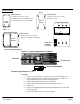
Cover Removal Size 2 Size 1 Remove Cover 1. Remove two cover screws. 2. Pull bottom of cover (held by cover screws) and lift cover off of top hinge. Cover Screws Remove Cover 1. Remove four cover screws. 2. Remove cover. Cover Screws L1 L2 L3 Control Board Size 3, 4 J2 J3 J4 D5 22 24 21 12 14 11 S0 S1 Remove Cover 1. Remove four cover screws. 2. Open cover (hinges on left side).
Section 1 General Information Optional Remote Keypad Installation The keypad may be remotely mounted using optional Baldor keypad extension cable. Keypad assembly (white - DC00005A-01; gray - DC00005A-02) comes complete with the screws and gasket required to mount it to an enclosure. When the keypad is properly mounted to a NEMA Type 4X enclosure, it retains the Type 4X rating.
AC Main Circuit Power Disconnect A power disconnect should be installed between the input power service and the control for a fail safe method to disconnect power. Protective Devices Recommended fuse sizes are based on the following: 175% of maximum continuous current for time delay. 300% of maximum continuous current for Fast or Very Fast action. Note: These general size recommendations do not consider harmonic currents or ambient temperatures greater than 40°C.
UL Required Fuses for Short Circuit Rating UL requires R/C fuses, special purpose fuses (JFHR2) or semiconductor fuses rated 700VAC be used to obtain the short circuit current ratings required by UL. Model Number MD9 to MD16 MD23 to MD30 MD44 MD59 MD72 to MD85 MD105 to MD146 MD174 to MD202 MD242 MD300 MD370 MD500 MD600 MD750 MD900 MD1100 MD1200 Fuse Manufacturer Bussman (300 KA A.I.C.) Ferraz (200 KA A.I.C.) Catalog Number Catalog Number 170M3110 6.6 URD 30 D08 A 0063 170M3112 6.
Figure 2-1 Power and Motor Circuit Connections 115/230VAC Note 2 L1 Note 1 L2 L3 Earth L1 * Circuit Breaker or *OL Note 6 Note 4, 8 L1 K1 is factory preset as the RUN" relay. L2 14 11 12 K1 X1 X2 Baldor Digital Soft–Start K2 T1 T2 T3 Note 2 T2 T3 Note 7 * AC Motor * Optional components not provided with control.
In–Delta Connections For Delta connected motors, the Soft–Start can be connected inside the delta windings. This connection method is shown in Figure 2-2. Figure 2-2 In–Delta Soft–Start Connections L1 L2 L3 L1 Earth Note 1 * Circuit Breaker Alternate * Fuse Connection Note 2 L2 L3 Note 1 * Optional components not provided with control.
Wire Size and Protection Devices Table 2-4 Control Wire Sizes and Tightening Torques Control Size Terminal Wire Gauge * AWG mm2 L1, L2, L3, T1, T2, T3 (M8 Stud for Ring connector) 1 Earth (Ground) Terminal 1/0 50 Terminal Torque Lb–in Nm 106 12 106 12 106 12 106 12 212 24 212 24 4.5 4.5 4.5 4.5 0.5 0.5 0.5 0.
Three Wire Control Figure 2-4 Three Wire Control Connection 115 / 230VAC Fuse Note: Add appropriately rated protective device for AC relay (snubber) or DC relay (diode). Neutral Stop Start R1 IC X1 X2 S1 S0 R1 IC OT OL IC= Input Contactor Coil OL= Thermal Overload Relay OT= Motor Thermal Overload Relay Baldor Digital Soft–Start 14 11 12 K1 24 21 22 K2 K1 is factory preset as the RUN" relay. * External hardware not provided with control. See Recommended Tightening Torques in Table 2-4.
NEMA 12/4 Installation When a NEMA12, NEMA4, NEMA4x OR IP65 enclosure is used, a separate Top of Ramp Bypass (or shunt) contactor must be connected in parallel with the soft–start control. This will allow a solid connection of the motor to the AC power lines and eliminate the heating effect caused by the SCR’s. At the completion of the start ramp (when full start voltage is obtained) a Bypass contactor is closed. This contactor is controlled by the “Top of Ramp” relay K2.
Reversing Contactor For this mode, the Stop Time must be set to zero. Also, allow a minimum of 350 milli seconds between the Forward and Reverse commands. Figure 2-7 Motor Reversing Connection To AC Input Forward Contacts Reverse Contacts MI To protect the control, be sure to add MOV protection. Refer to Appendix D for additional information.
Installation 1. Remove cover. (See cover removal described previously in this section.) 2. Mount the panel or enclosure to the mounting surface. The panel or enclosure must be securely fastened to the mounting surface. Refer to the mounting dimensions in Section 6 of this manual. Shock Mounting If the control will be subjected to levels of shock greater than 1G or vibration greater than 0.5G at 10 to 60Hz, the control should be shock mounted. 3.
Section 3 Operation Overview The start–up procedure will help get your system up and running quickly and will allow motor and control operation to be verified. This procedure assumes that the Control and Motor are correctly installed (see Section 2 for procedures) and that you have a basic understanding of the keypad programming & operation procedures. 1. Read the Safety Notice and Precautions in section 1 of this manual. 2. Mount the control. 3.
Start–Up Procedure This procedure assumes that this is the first time the control and motor have been started. The normal start–up procedure would be as follows: 1. Apply X1, X2 Control Voltage power (115VAC). 2. Apply three phase power. The display should show “Stopped & Ready”. 3. Press ENTER and the display should show “Applications”. 4. Press ENTER and the display should show “Settings”. 5. Press the UP or DOWN Arrows and select the desired type of motor load. 6.
Operating Modes System Status Mode Description During normal operation, the display shows the status of operation. Menu Mode In the menu mode, a flashing cursor is displayed. Use the ⇑ or ⇓ keys to scroll through the menu items. Use the ENTER key to select a menu item or move to the next level. 183 A Shows that Optimized operation is selected and the load current is 183 amperes. Display APPLICATIONS BASIC Comments V represents blinking cursor.
Menu Structure Figure 3-2 Menu Structure Diagram Level 0 Level 1 Level 2 Level 3 ENTER ENTER ENTER ENTER Stopped and ready Applications Auto features Auto features Basic Basic Advanced Advanced Permanent store Permanent store Password Password Inputs Settings Auto Jog (Off) Auto Pedestal (Off) Auto end start (Off) Auto stop (Off) Auto end stop (Off) Auto bypass (On) Auto 3MC (On) Auto off (Off) Stop smoothing (Off) Starting (Keypad) Start pedestal Start time (5s) Stop pedestal (10%) Stop time
Menu Navigation Examples Menu Navigation Action Apply Control Voltage (115VAC) This example shows how to go to the Inputs menu and map an input parameter. Description Display Comments Keypad Display shows this opening message. Baldor Soft Start Logo display for 2 seconds. If no faults the display will show this message. Stopped & Ready System Status mode. Press ENTER key APPLICATIONS AUTO FEATURES Press ENTER to access menu mode. Press ⇓ key Scroll to the AUTO FEATURES menu.
Changing the Power–up Settings & Select Keypad Control When the Control Supply (115VAC) power is first applied, the control loads the parameter settings into working memory. You may change any of these parameters and operate a motor with the changed settings. However, if these values are not saved they will be lost the next time power is removed. You can save the new values as power–up values so they will be loaded the next time Control Supply power is turned off and turned back on.
Motor Starting Definitions Term Definition Starting Selectable in Basic Menu as either Keypad or Remote starting method. Voltage Pedestal Initial voltage applied to motor after the 3 cycle power–up ramp. Programmed as parameter 11 or as Start Pedestal in Basic Menu. Kick Pedestal For traction or “frozen” loads, this boost pulse of higher voltage helps the load to start moving. Kick Start is in the Advanced menu. Kick Pedestal is parameter 13 or as Kick Pedestal in Advanced menu.
Keypad Starting and Running the Motor with Factory Settings Action Apply Control Voltage (115VAC) Description Display Comments Keypad Display shows this opening message. Baldor Soft Start Logo display for 2 seconds. If no faults the display will show this message. Stopped & Ready System Status mode. Press ENTER key APPLICATIONS AUTO FEATURES Press ENTER key Access Level 1 Application Menu. Settings Default (Keypad) Press ⇓ key two times Scroll to the correct application.
Keypad Starting and Running the Motor in Optimise Mode Action Apply Control Voltage (115VAC) Description Display Comments Keypad Display shows this opening message. Baldor Soft Start Logo display for 2 seconds. If no faults the display will show this message. Stopped & Ready System Status mode. Press ENTER key APPLICATIONS AUTO FEATURES Press ENTER key Access Level 1 Application Menu. Settings Default (Keypad) Press ⇓ key two times Scroll to the correct application.
Motor Stopping Definitions Term Definition Stop Pedestal Voltage Stop Pedestal Voltage is the percentage of line voltage applied to the motor after a stop command. Programmed as parameter 16 or as Stop Pedestal in Basic Menu. Stop Time Time in seconds after a stop command to ramp down the motor voltage (Stop Time 1 or 2) Stop Time 1 with low voltage ramp active. Stop Time 2 with no low voltage ramp. Programmed as parameter 17 or as Stop Time in Basic Menu.
Section 4 Parameter Index Menu Descriptions Basic Menu Block Title Parameter Description Basic Starting Keypad – Allows motor starting and stopping by pressing Start/Stop key on keypad. Remote – Allows motor starting and stopping by applying or removing 115VAC at terminals S0 and S1 of the control board. Start Pedestal Start Pedestal Voltage – end of stop smoothing and beginning of low voltage ramp to zero volts (if low voltage ramp is active).
Applications Menu Continued Name Start Pedestal % Start Time Current Limit Level Small Pump 10 % 5 S 3.5 *FLC Stop Pedestal % Stop Time Current Limit Time Optimise Rate Auto Pedestal Auto End Start Auto Bypass Auto 3MC Low Voltage SoftStop Soft Stop Smoothing Name Start Pedestal % Start Time Current Limit Level Large Pump 10 % 7 S 3.
Advanced Menu Block Title Parameter Description Advanced Current Rated Current – (View Only) this value is the continuous current rating of the control. Low Current – If on, activates low current trip protection. Useful to detect a low current condition (broken belt, coupling, pump etc.) on driven equipment. Low Current Level – The value of the low current trip detection. Value can be 0 to 100% of the Rated Current parameter value. Parameter 28.
Advanced Menu Continued Block Title Parameter Description Advanced Contactor Delay A delay is required when an input contactor is energized by the soft–start “Run” relay. This delay allows bouncing contactor armature to settle during the “Closed” position. Value can be 20 to 800 milliseconds. Parameter 71. Trip Sensitivity A numerical value that sets the sensitivity level for all trips. A larger number provides slower response to a trip. Value can be 1 to 15. Parameter 72.
Permanent Store Menu Block Title Parameter Description Permanent Store Save Parameters Saves all parameter values and overwrites previously saved values. Power on Parameters Restores all parameter values to the values that were last saved (last power up cycle). All parameter values changes since last power up are overwritten. Display blinks twice to confirm reset is complete. Default Parameters Restores all parameter values to the factory settings. All parameter values are overwritten.
Outputs Menu The internal LED, four digital outputs and two analog outputs can be individually defined as desired. Each digital output can be assigned positive or inverse logic. Block Title Parameter Description Outputs LED Available only on size 2 and 3 controls, this Red LED can represent a variety of status conditions. The LED is located on the control board. K1 Relay output with Form C (1 N.O. and 1 N.C.) single pole, double throw contacts. Contacts are rated for 10Amp @ 250VAC.
Mapping to an Output Relay Most status values are stored in memory as status words.
Parameter Descriptions Title Parameter Version 5MC (4/2/01) Password Advanced P# P0 P1 P2 P3 P4 P5 P6 Parameter Dummy Parameter Station Number Country Software Type Software Version Password Value Firing Mode Basic P7 Protection Mode Parameters P8 Status 1 P9 Status 2 P10 Status 3 Basic P11 Start Pedestal Advanced P12 P13 P14 Start Time Kick Pedestal Kick Time Auto Features P15 P16 P17 P18 Dwell Time Stop Pedestal Stop Time Auto Config Advanced P19 Optimise Rate Basic 4-8 Paramet
Title Parameters P# P20 Parameter Reference PF (Power Factor) Description The calculated power factor to optimize the control loop. P21 Present PF (Power Factor) The present power factor of the motor (load). P22 Delay Angle (SCR OFF time) The period (in degrees) that the thyristors are in the OFF state. P23 Maximum Optimizing Delay Sets the maximum delay angle (max degrees that the thyristors are OFF) used during the optimizing mode.
Title Parameters Continued P# P51 User Flags 1 P52 User Flags 2 P53 User Flags 3 P54 I/O Polarity Determines the polarity of the digital inputs and outputs. A Bit set=0; is negative logic. A Bit set=1; is positive logic. Example: P54, Bit0=1 (K1 mapped to Main Contactor), P57=52, P58=00100000 P52, Bit 5=1 will cause K1 to close.
Title Parameters Continued MN850 P# P60 Parameter K2 Bit Mask (P59 bit selected for K2) Description Sets the bit in the parameter selected by P59 that operates the relay K2 on the control card. The preset is P8:Status 1, Bit3 (Top of Ramp or Full Volts). (P60 operates with P59).
Title Advanced Current Parameters P# P71 Parameter Contactor Delay (after start command) Description Sets the delay time between the request to actuate K1 and the start of firing the thyristors. P72 Trip Sensitivity (1=fastest trip) Unused P73 Last Trip (Most Recent Trip) P73 stores the most recent trip code for the most recent fault. Trip code definitions are as follows: 0 Not Used 1 Phase Loss Fault. One or phases of the incoming three phase AC power is missing. Check fuses etc.
Section 1 General Information Title Parameters Continued Parameters Continued MN850 86 P# Parameter Auto Config 2 (for 2nd param set) Auto configuration flags for the second parameter set. Description Definition (Preset Value) Bit0= Unused Bit1= Auto 3MC (1, enable auto removal of low voltage ramp for high start pedestals) Bit2= Auto Bypass (1, enable automatic bypass contactor detection). Bit3= Auto Jog (0, disable jog detection. If enabled a stop request within 0.
Section 1 General Information Title Parameters Continued Parameters Continued P# 100 Parameter Flag1 O/P Destination Mask Description The bit mask for destination flag parameter. 101 Flag2 I/P Source Address Address of source flag parameter. (Parameter 102 is the mask for P101.) 102 Flag2 I/P Source Mask The bit mask for source flag parameter. 103 Flag2 O/P Destination Address Address of destination flag parameter. (Parameter 104 is the mask for P103.
Section 5 Troubleshooting Safety Notice Be sure to read and understand all notices, warning and caution statements in Section 1 of this manual. If you have any questions about the safe operation of this equipment, please contact your Baldor representative before you proceed. Preliminary Checks In the event of trouble, disconnect all input power to the control and perform these preliminary checks. Power Off Checks 1. 2. 3. 4. 5. Check all connections for tightness and signs of overheating.
Table 5-2 Troubleshooting Guide INDICATION Unit fails to start CORRECTIVE ACTION LED’s on control card are OFF and no error messages displayed: 1. Verify that 115VAC is present at X1 and X2 terminals. 2. Verify that 9VAC is present at terminal J2 (see Section 2 cover removal). Green power LED is ON and no error messages displayed: 1. Control board or other component may be defective. Contact Baldor. Unit trips during start 1.
Table 5-2 Troubleshooting Guide Continued INDICATION Initial motor kick then bad start CORRECTIVE ACTION Verify that AC input power and motor power wires are not reversed. (The motor will give an initial kick then start very roughly.) Current is not displayed 1. Verify the current transformer connections at J3 control terminal. 2. Verify that the soft–start control is correctly sized. Motor does not accelerate 1. Verify the Current Limit parameter value and increase if necessary. 2.
Electrical Noise Considerations All electronic devices are vulnerable to significant electronic interference signals (commonly called “Electrical Noise”). At the lowest level, noise can cause intermittent operating errors or faults. From a circuit standpoint, 5 or 10 millivolts of noise may cause detrimental operation. For example, analog speed and torque inputs are often scaled at 5 to 10VDC maximum with a typical resolution of one part in 1,000. Thus, noise of only 5 mV represents a substantial error.
Section 6 Specifications and Product Data Identification Three Phase Digital Soft–Start MD 7 016 C B Control Type MD – Multipurpose Digital Input Voltage 7- 208, 230, 460VAC 8- 230, 460, 575VAC Ampere Rating 009- 9 Amp 016- 16 Amp 023- 23 Amp 030- 30 Amp 044- 44 Amp 059- 59 Amp 072- 72 Amp 085- 85 Amp 105- 105 Amp 146- 146 Amp 174- 174 Amp 202- 202 Amp 242- 242 Amp 300- 300 Amp 370- 370 Amp 500- 500 Amp 600- 600 Amp 750- 750 Amp 900- 900 Amp 1100- 1100 Amp 1200- 1200 Amp MN850 Enclosure A- Open Kit B- Ope
Input Ratings Input Voltage Range MD7–XXX = 208/230/460 VAC MD8–XXX = 230/460/575 VAC Phase Three Phase Input Frequency 60/50 HZ ± 5% Overload Rating Continuous 115% of FLA; 350% for 30 seconds.
Standard Duty: Agitator, Compressor, Centrifuge, Fan, Blower, Chiller, Escalator, Pump, Bandsaw, Low Inertia Fan, Small Pump. Medium Duty: Mill, Conveyor, Drilling Press, Reciprocating Compressor, Elevator, Screw Feeder, Grinder, Hammer Press, Mixer, Large Pump, High Inertia Fan, Pelletizer, Pulper, Flywheel Press, Positive Displacement Pump, Circular Saw, Vibrating Screens. Heavy Duty: Rock Crusher, Pulverizer, Separator, Chipper, Screw Compressor.
Mounting Dimensions Size 1 0.23 (M6) Slot 4 Places 16.31 (414) 14.93 (379) 0.23 (M6) Hole 4 Places Ground Ground 1.41 (36) 4.9 (125) 8.74 (222) 7.68 (195) 5.9 (150) Model # –9 –16 –23 –30 –44 –59 –72 –85 –105 –146 6-4 Specifications and Product Data Weight lb (kg) 16.1(7.3) 16.1(7.3) 16.1(7.3) 16.1(7.3) 16.1(7.3) 18.3(8.3) 18.3(8.3) 18.3(8.3) 18.3(8.3) 18.3(8.
Mounting Dimensions Continued Size 2 Ground 20.47 (520) 19.68 (500) 0.23 (M6) Hole 2 Places 0.23 (M6) Slot 2 Places 9.84 (250) 10.43 (265) 13.38 (340) Model # –174 –202 –242 –300 –370 MN850 Weight lb (kg) 34.6(15.7) 34.6(15.7) 48.5(22) 48.5(22) 48.
Mounting Dimensions Continued Size 3 24.01 (610) 22.64 (575) 0.39 (M10) Hole 3 Places 0.39 (M10) Slot 3 Places 1.38(35) 9.84 (250) 9.84 (250) 15.75 (400) 3.44 (87.5) 26.58 (675) Model # –500 –600 –750 –900 6-6 Specifications and Product Data Weight lb (kg) 143.3(65) 143.3(65) 158.8(72) 158.
Mounting Dimensions Continued Size 4 12.68 (322) 25 (635) 10.87 (276) 24.45 (621) 5.95 (151) Air Flow 7.88 (200) 7.88 (200) 3.94 (100) 4.13 (105) 1.9 7 (50) 7.59 (193) m10 T1, T2, T3 7.59 (193) 6.58 (167) Model # –1100 –1200 MN850 4.53 (115) L1, L2, L3 Weight lb (kg) 158.8 (72) 165.
6-8 Specifications and Product Data MN850
Appendix A CE Guidelines CE Declaration of Conformity Baldor indicates that the products are only components and not ready for immediate or instant use within the meaning of “Safety law of appliance”, “EMC Law” or “Machine directive”. The final mode of operation is defined only after installation into the user’s equipment. It is the responsibility of the user to verify compliance.
Using CE approved components will not guarantee a CE compliant system! 1. The components used in the drive, installation methods used, materials selected for interconnection of components are important. 2. The installation methods, interconnection materials, shielding, filtering and grounding of the system as a whole will determine CE compliance. 3. The responsibility of CE mark compliance rests entirely with the party who offers the end system for sale (such as an OEM or system integrator).
EMC Installation Instructions To ensure electromagnetic compatibility (EMC), the following installation instructions should be completed. These steps help to reduce interference. Consider the following: • Grounding of all system elements to a central ground point • Shielding of all cables and signal wires • Filtering of power lines A proper enclosure should have the following characteristics: A) All metal conducting parts of the enclosure must be electrically connected to the back plane.
A-4 Appendix MN850
Appendix B Parameter Values Version 5MC (4/2/01) Title Parameter P# Parameter Read Only Parameter Values Adjustable Range Factory User Setting P0 Dummy Parameter 0–255 0 P1 Station Number 1–99 1 P2 Country 1–255 44 (England) P3 Software Type Factory Set Read Only P4 Software Version Factory Set Read Only Password P5 Password Value 0–255 0 Advanced P6 Firing Mode 0–3 0 Basic P7 Protection Mode 0–192 192 (Full + Optimize) Parameters P8 Status 1 0–255 1 (bit 0000000
Read Only Parameter Values Title Parameters Advanced Current B-2 Applications P# Parameter Adjustable Range Factory P36 % Overload (status only) 0–100% (100%=Tripped) 0% P37 Chassis Temperature 0–255 0 P38 Pot1 0–255 0 P39 Pot2 0–255 0 P40 Pot3 0–1 0 P41 DC I/P 0–12 0VDC P42 Thermistor 0–255 0 P43 4–20mA I/P 0–20.4 0mA P44 TEMP Trip Level 20–255 30 P45 4–20mA Map 0–125 0 (parameter #) P46 4–20mA Set Level 0.08–20.32 10.
Section 1 General Information Read Only Parameter Values Title Parameters MN850 P# Parameter Adjustable Range Factory User Setting P74 2nd Last Trip 1–16 (Status Code) 0 P75 3rd Last Trip 1–16 (Status Code) 0 P76 4th Last Trip 1–16 (Status Code) 0 P77 5th Last Trip (Oldest trip) 1–16 (Status Code) 0 P78 Protection Mode 2 0–192 192 (Full + Optimize) P79 Start Pedestal 2 10–60% 50 (% of line volts) P80 Start Time 2 1–255 seconds 5 seconds P81 Kick Pedestal 2 60–90% 75 (%
Section 1 General Information Read Only Parameter Values Title Parameters B-4 Applications P# Parameter Adjustable Range Factory P111 User Parameter 0–255 0 P112 Status 4 0–255 0 (bit 00000000) P113 Drive Type 0–255 0 P114 Baud Rate 0–4 0 P115 Selected App 0–9 0 P116 5MC Inhibit Time (restart not allowed) 0–63.75 minutes 0 minutes P117 Command Source Unused P118 Action On Bus Error 0–3 0 P119 Preset Parameter Number to Display 0.
Appendix C Replacement Parts Voltage Independent Parts PART No.
575VAC Parts PART No.
Appendix D Voltage Surge Protection Grounding Proper grounding is extremely important. The symptoms produced by improper grounding are obvious. Sometimes filters and other expensive devices are added to reduce the effects of problems caused by poor grounding. There can be several reference points (neutrals) in a circuit but there should always only be one ground point. Neutral and ground are not the same.
Figure D-2 WYE Configurations Symbol Ungrounded Control Enclosure L1 L2 L3 T1 T2 T3 L1 L2 L3 Do not ground MOV. Cut off green wire and insulate (cap off) with wire nut.
Figure D-3 Delta Configurations Symbol Control Enclosure Ungrounded L1 L2 L3 T1 T2 T3 L1 L2 L3 Do not ground MOV. Cut off green wire and insulate (cap off) with wire nut. MOV Corner or Center–Tap Grounded Symbol Control Enclosure L1 L2 L3 T1 T2 T3 L1 L2 L3 MOV Do not ground MOV. Cut off green wire and insulate (cap off) with wire nut.
D-4 Voltage Surge Protection MN850
Appendix E MN850 Appendix E-1
Section 1 General Information Remote Keypad Mounting Template 4.00 2.500 (A) (A) Four Places Tapped mounting holes, use #29 drill and 8-32 tap (Clearance mounting holes, use #19 or 0.166″ drill) 5.500 4.810 1-11/16″ diameter hole Use 1.25″ conduit knockout (B) 1.340 (A) (A) 1.250 E-2 Appendix Note: Template may be distorted due to reproduction.
BALDOR ELECTRIC COMPANY P.O. Box 2400 Ft. Smith, AR 72902–2400 (479) 646–4711 Fax (479) 648–5792 www.baldor.