MOTION CONTROL NextMove BX II Motion Controller Installation Manual 9/02 MN1904
Contents 1 General Information . . . . . . . . . . . . . . . . . . . . . . . . . . . . . . . . . 1-1 2 Introduction . . . . . . . . . . . . . . . . . . . . . . . . . . . . . . . . . . . . . . . . 2-1 2.1 NextMove BX II features . . . . . . . . . . . . . . . . . . . . . . . . . . . . . . . . . 2-1 2.2 Receiving and inspection . . . . . . . . . . . . . . . . . . . . . . . . . . . . . . . . 2-2 2.2.1 2.3 3 Units and abbreviations . . . . . . . . . . . . . . . . . . . . . . . . . . . . . . . . . .
.7.5 4.7.6 4.7.7 4.7.8 4.7.9 4.8 5 4-17 4-18 4-20 4-21 4-21 Reset states . . . . . . . . . . . . . . . . . . . . . . . . . . . . . . . . . . . . . . . . . . . 4-22 4.8.1 4.9 Connecting Baldor HMI Operator Panels . . . . . . . . . . . . . . . . . . . . . . . . . . . RS422 / RS485 - X14 . . . . . . . . . . . . . . . . . . . . . . . . . . . . . . . . . . . . . . . . . . . CAN connectors - X16 & X17 . . . . . . . . . . . . . . . . . . . . . . . . . . . . . . . . . . . . CANopen . . . . . . . . . . . . .
6 Troubleshooting . . . . . . . . . . . . . . . . . . . . . . . . . . . . . . . . . . . . 6-1 6.1 Introduction . . . . . . . . . . . . . . . . . . . . . . . . . . . . . . . . . . . . . . . . . . . . 6.1.1 6.1.2 6.2 NextMove BX II indicators . . . . . . . . . . . . . . . . . . . . . . . . . . . . . . . . 6.2.1 6.2.2 6.2.3 6.2.4 7 Problem diagnosis . . . . . . . . . . . . . . . . . . . . . . . . . . . . . . . . . . . . . . . . . . . . . . SupportMet feature . . . . . . . . . . . . . . . . . . . . . . .
iv Contents MN1904
1 General Information 1 LT0158A01 Copyright Baldor (c) 2002. All rights reserved. This manual is copyrighted and all rights are reserved. This document or attached software may not, in whole or in part, be copied or reproduced in any form without the prior written consent of BALDOR. BALDOR makes no representations or warranties with respect to the contents hereof and specifically disclaims any implied warranties of fitness for any particular purpose.
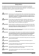
Safety Notice Only qualified personnel should attempt the start-up procedure or troubleshoot this equipment. This equipment may be connected to other machines that have rotating parts or parts that are controlled by this equipment. Improper use can cause serious or fatal injury. Only qualified personnel should attempt to start-up, program or troubleshoot this equipment. Precautions WARNING: Be sure that you are completely familiar with the safe operation and programming of this equipment.
2 Introduction 2 2.1 NextMove BX II features NextMove BX II is a high speed multi-axis intelligent motion controller, supporting up to four servo axes. NextMove BX II features the Mint motion control language. Mint is a structured form of Basic, custom designed for motion control applications. It allows you to get started very quickly with simple motion control programs. In addition, Mint includes a wide range of powerful commands for complex applications.
2.2 Receiving and inspection When you receive your NextMove BX II, there are several things you should do immediately: 1. Check the condition of the packaging and report any damage immediately to the carrier that delivered your NextMove BXII. 2. Remove the NextMove BXII from the shipping container. The packing materials may be retained for future shipment. 3. Verify that the catalog number of the NextMove BX II you received is the same as the catalog number listed on your purchase order.
2.3 Units and abbreviations The following units and abbreviations may appear in this manual: V ............... W .............. A ............... Ω ............... µF . . . . . . . . . . . . . . pF . . . . . . . . . . . . . . mH . . . . . . . . . . . . . Volt (also VAC and VDC) Watt Ampere Ohm microfarad picofarad millihenry Φ............... ms . . . . . . . . . . . . . . µs . . . . . . . . . . . . . . ns . . . . . . . . . . . . . . phase millisecond microsecond nanosecond Kbaud . . . . . . . . . . .
2-4 Introduction MN1904
3 Basic Installation 3 3.1 Introduction You should read all the sections in Basic Installation. It is important that the correct steps are followed when installing the NextMove BX II. This section describes the mechanical installation and power requirements of the NextMove BX II. 3.1.1 Power sources An external (customer supplied) 24VDC logic supply is required.
3.1.3 Tools and miscellaneous hardware H Your PC operating system user manual might be useful if you are not familiar with Windows H A small screwdriver (supplied) with a blade width less than 2.5mm (1/10 in). H M5 screws or bolts for mounting the NextMove BX II H Crimping tool. A connector kit is supplied with your NextMove BX II, containing a number of useful connectors and accessories. 3.1.
3.2 Mechanical installation and location requirements It is essential that you read and understand this section before beginning the installation. The safe operation of this equipment depends upon its use in the appropriate environment. The following points must be considered: H The NextMove BX II must be installed indoors, permanently fixed and located so that it can only be accessed by service personnel using tools. H The maximum suggested operating altitude is 2000m (6562ft).
3.2.1 Mounting the NextMove BX II Ensure you have read and understood the Mechanical installation and location requirements in section 3.2. Mount the NextMove BX II on its rear side, the side opposite the front panel. The NextMove BX II must be mounted upright to ensure adequate cooling. M5 bolts or screws should be used. 302 (11.9) 58.5 (2.3) All dimensions shown as mm (inches) 203 (8.0) 312 (12.3) 194 (7.6) 40 (1.
4 Input / Output 4 4.1 Introduction This section describes the location and purpose of each connector on the NextMove BX II. The following conventions will be used to refer to the inputs and outputs: I/O . . . . . . . . . . . . . . DIN . . . . . . . . . . . . . DOUT . . . . . . . . . . . AIN . . . . . . . . . . . . . AOUT . . . . . . . . . . . Input / Output Digital Input Digital Output Analog Input Analog Output 4.
4.
4.4 Power connections A 24VDC, 2A supply must be provided to power the control electronics. It is recommended that a separate fused 24V supply is provided for the NextMove BX II, with the fuse rated at 4A maximum. If other devices are to be powered from the same 24V supply, a filter (Baldor catalog number FI0014A00) should be installed to isolate the NextMove BX II from the rest of the system. 4.4.1 Power - X8 Location Connector X8 (Mating connector: Weidmüller BL 3.5/10, 3.
4.5 Analog I/O The NextMove BX II provides: H Eight 12-bit resolution analog inputs, available on connector X3. H Four 14-bit resolution analog outputs, available on connector X7. Sections 4.5.1 to 4.5.2 describe each analog input and output. 4.5.1 Analog inputs - X3 Location Pin Connector X6 (Mating connector: Weidmüller BL 3.5/10, 3.5mm pitch) Name MintMT keyword / description 1 AIN0 ADC.0 2 AIN1 ADC.1 3 AIN2 ADC.2 4 AIN3 ADC.3 5 AIN4 ADC.4 6 AIN5 ADC.5 7 AIN6 ADC.
H Pseudo differential, bipolar (ADCMODE 3): Inputs are used in pairs (0 and 1, 2 and 3, 4 and 5, 6 and 7) to create four differential inputs. Within each pair, the odd numbered input is the negative input, and the even numbered input is the positive input. The input range is ±2.5V. H True differential (ADCMODE 5): Inputs are used in pairs (0 and 1, 2 and 3, 4 and 5, 6 and 7) to create four differential inputs.
4.5.2 Analog outputs (Demands) - X7 Location 1 Pin 10 Connector X7 (Mating connector: Weidmüller BL 3.5/10, 3.5mm pitch) Name MintMT keyword / description 1 Demand0 DAC.0 2 AGND Analog ground 3 Demand1 DAC.1 4 AGND Analog ground 5 Demand2 DAC.2 6 AGND Analog ground 7 Demand3 DAC.3 8 AGND Analog ground 9 AGND Analog ground 10 Shield Shield connection Description Four independent command outputs Output range: ±10VDC (±10mV). Resolution: 14-bit (accuracy ±1.22mV).
4.6 Digital I/O There are a total of 20 digital inputs. Inputs DIN0 to DIN15 are general purpose inputs, which can be configured in Mint for any of the following functions: H forward limit (end of travel) input on any axis H reverse limit (end of travel) input on any axis H home input on any axis H drive error input on any axis H controlled stop input on any axis. Inputs DIN16 to DIN19 are known as fast position interrrupts and can only be used to latch position.
4.6.1 Digital inputs - X1 Location Connector X1 (Mating connector: Weidmüller BL 3.5/10, 3.5mm pitch) Pin Name Mint keyword / description 1 DIN8 INX.8 2 DIN9 INX.9 3 DIN10 INX.10 4 DIN11 INX.11 5 DIN12 INX.12 6 DIN13 INX.13 7 DIN14 INX.14 8 DIN15 INX.15 9 CREF Common connection 10 Shield Shield connection Description Eight general purpose optically isolated AC digital inputs. Sampling interval: 1ms NextMove BX II Vcc 2k2 Mint INX.
The inputs are conditioned using Schmitt trigger buffers. If an input is configured as edge triggered, the triggering pulse must have a duration of at least 1ms (one software scan) to guarantee acceptance by Mint. The use of shielded cable for inputs is recommended. Active high: connect +24VDC to the input and 0V to pin 9 (CREF). The digital inputs will be active when a voltage of +24VDC (greater than 12VDC) is applied to them and will sink a current of approximately 11mA each.
4.6.3 Digital inputs (Interrupts) - X6 Digital inputs FASTIN0 to FASTIN3 can be used as high speed position latches, allowing any combination of axes to be captured by the hardware. Using FASTIN0, the latency between input triggering and capture is 30µs. Using FASTIN1 to FASTIN3, latency is 1ms. Special Mint keywords (beginning with the letters FAST...) allow specific functions to be performed as a result of fast position inputs becoming active. See the Mint help file for details.
4.6.4 Digital outputs - X4 Location 1 Pin 10 Connector X4 (Mating connector: Weidmüller BL 3.5/10, 3.5mm pitch) Name Mint keyword / description 1 DOUT0 OUTX.0 2 DOUT1 OUTX.1 3 DOUT2 OUTX.2 4 DOUT3 OUTX.3 5 DOUT4 OUTX.4 6 DOUT5 OUTX.5 7 DOUT6 OUTX.6 8 DOUT7 OUTX.7 9 USR V+ Customer power supply V+ CGND Customer power supply ground 10 Description Eight general purpose optically isolated digital outputs.
4.7 Other I/O 4.7.
4.7.2 Encoder input frequency The maximum encoder input frequency is affected by the length of the encoder cables. The theoretical maximum frequency is 7.5 million quadrature counts per second. This is equivalent to a maximum frequency for the A and B signals of 1.87MHz. However, the effect of cable length is shown in the Table 1: Encoder Frequency Maximum cable length meters feet 1.3MHz 2 6.56 500kHz 10 32.8 250kHz 20 65.6 100kHz 50 164.0 50kHz 100 328.1 20kHz 300 984.
4.7.3 Relay and user power - X5 Location Pin Connector X5 (Mating connector: Weidmüller BL 3.5/10, 3.
4.7.4 RS232 - X15 Location Top panel, connector X15 Pin Name 1 Shield 2 RXD 3 TXD 6 9 1 5 4 DTR (internally connected to pin 6) 5 0V 6 DSR (internally connected to pin 4) 7 RTS 8 CTS 9 0V Description RS232 connections on a single 9-pin male D-type connector The NextMove BX II has a full-duplex RS232 serial port with the following preset configuration: H 9600 baud H 1 start bit H 8 data bits H 1 stop bit H No parity H Hardware handshaking lines (RS232) RTS and CTS must be connected.
RS232 NextMove BX II (DTE) COM RXD 2 2 RXD TXD 3 3 TXD GND 5 5 GND RTS 7 7 RTS CTS 8 8 CTS 9-- pin Computer COM Port (DCE / DTE) Connect overall shield to connector backshell. Figure 9 - RS232 serial port connections The maximum recommended cable length is 3m (10ft) at 57.6Kbaud. When using lower baud rates, longer cable lengths may be used up to maximum of 15m (49ft) at 9600 baud.
4.7.5 Connecting Baldor HMI Operator Panels Baldor HMI Operator Panels use a 15-pin male D-type connector (marked PLC PORT), but the NextMove BX II RS232 connector is a 9-pin male D-type connector.
4.7.6 RS422 / RS485 - X14 If you will be using RS422 / RS485 and your PC does not have an RS422 / RS485 connector, an RS232 to 4-wire RS422 / RS485 converter will be required. These commercially available devices convert the signals from the PC RS232 port to the signals necessary for RS422 / RS485 communications. Special care must be taken with the pin assignment on all RS422 / RS485 devices, as this can differ between products. Connectors might need to be rewired to provide the correct pin assignment.
Network master TX+ Network slave RX+ Twisted pairs TX- RX- RX+ TX+ RXDGND TX- TR DGND TR Network slave RX+ RX- Final slave shown with terminating resistor, TR, typical value 120Ω. TX+ TXDGND Connect overall shield to connector backshell. Figure 12 - 4-wire RS485 multi-drop connections Each TX/RX network requires a termination resistor at the final RX connection, but intermediate devices must not be fitted with termination resistors.
4.7.7 CAN connectors - X16 & X17 CAN (Controller Area Network) offers very reliable serial communications over a two wire twisted pair cable. In an industrial environment, the probability of an undetected error is 4.7x10⁻¹¹. CAN also offers high speed data transfer (up to 1Mbit/s, dependent on bus length) and low cost multiplex wiring schemes. CAN is optimized for the transmission of small data packets and therefore offers fast update of I/O devices (peripherals) connected to the bus.
4.7.8 CANopen CANopen is a networking system based on the serial bus CAN. It uses the international CAN standard ISO 11898 as the basis for communication. The Mint firmware implements a CANopen protocol on CAN bus 1, based on the ‘Communication Profile’ CiA DS-301, which supports both direct access to device parameters and time-critical process data communication. This provides support for a range of Baldor and third-party devices. The CANopen channel is available on both CAN connectors.
4.8 Reset states During power up, NextMove BX II is held in a safe non-operational state known as hardware reset. It will also go into hardware reset if the 24V logic supply drops below approximately 18V. This prevents uncontrolled operation due to the electronics losing power. When NextMove BX II is in hardware reset for any reason, most of the controlled interfaces fall into known states. It is also possible for NextMove BX II to be in a state known as software reset.
4.9 Connection summary - minimum system wiring As a guide, Figure 14 shows an example of the typical minimum wiring required to allow the NextMove BX II and a single servo amplifier (motor drive) to work together. Servo amplifier (axis 0) Host PC Serial communication NextMove BXII Error out Demand + Demand Enable* Gnd* Encoder output from drive or motor Common earth/ground +24V supply * Note: This diagram shows the relay contacts being used as a switch across the servo amplifier’s enable input.
NextMove BX II connector Name of signal Function Servo amplifier connection (Note: drive may be labelled differently) X1 DIN8 Error input Error output X5 Relay COM Common connection of relay Enable input Relay NC Normally closed connection of relay Ground Demand0 Command signal for axis 0 Demand+ input AGND Reference for analog signals Demand- input Shield Cable shield (Not connected) X9 (Encoder 0) Position feedback for axis 0 Encoder out (or direct from motor) X8 +24V Logic s
5 Operation 5 5.1 Introduction Before powering the NextMove BX II you will need to connect it to the PC using a serial cable and install the supplied PC software WorkBench v5. This software includes a number of tools to allow you to configure, tune and program the NextMove BX II. If you do not have experience of software installation or Windows applications you may need further assistance for this stage of the installation 5.1.
5.1.5 Power on checks If at any time one of the Axis LEDs is illuminated red, this indicates that the NextMove BX II has detected a fault - see section 6. 1. Turn on the 24VDC supply. 2. After a brief test sequence the Status display should show the node number, for example (the factory preset). If the display is not lit then re-check the power supply connections. The NextMove BX II is now ready to be configured using WorkBench v5.
5.2 WorkBench v5 WorkBench v5 is a fully featured application for programming and controlling the NextMove BX II. The main WorkBench v5 window contains a menu system, the Toolbox and other toolbars. Many functions can be accessed from the menu or by clicking a button - use whichever you prefer. Most buttons include a ‘tool-tip’; hold the mouse pointer over the button (don’t click) and its description will appear. 5.2.
5.2.2 Starting WorkBench v5 1. On the Windows Start menu, select Programs, WorkBench v5, WorkBench v5. WorkBench v5 will start, and the Tip of the Day dialog will be displayed. You can prevent the Tip of the Day dialog appearing next time by removing the check mark next to Show tips at startup. Click Close to continue. 2. In the opening dialog box, click Start New Project... .
3. In the Select Controller dialog, go to the drop down box near the top and select the PC serial port to which the NextMove BX II is connected. (If you are unsure which PC serial port is connected to the NextMove BX II, select Scan all serial ports. During the detection process, a dialog box may be displayed to tell you that WorkBench v5 has detected new firmware. Click OK to continue.) Click Scan to search for the NextMove BX II.
5.3 Configuring an axis The NextMove BX II is capable of controlling up to 4 servo axes, depending on model. Axis numbering always begin at 0. For example, a four axis model has axes numbered 0, 1, 2 and 3. This section describes the basic setup for a single axis. Note: The NextMove BX II is also capable of controlling up to 4 ‘virtual’ axes. A virtual axis allows most Mint commands to be executed as normal, with the virtual axis simulating position and velocity information for any motion performed.
4. Click in the Scale box and type a value. 5. Click Apply. This immediately sets the scaling factor for the selected axis. It will remain in the NextMove BX II until another scale is defined, or power is removed. 5.3.2 Setting the drive enable output The drive enable output allows NextMove BX II to disable the drive in the event of an error. Each axis can be configured with its own drive enable output, or can share an output with other axes.
4. If you are going to use the relay, drag the grey Relay0 icon to the grey X axis icon on the right of the screen. To configure multiple axes to use the relay, repeat this step for the other axes. If you are using a digital output, drag the bright blue OUT icon to the grey X axis icon on the right of the screen. To configure multiple axes with the same drive enable output, repeat this step for the other axes. 5. Click Apply at the bottom of the screen.
5.4 Testing and tuning This section describes the method for testing and tuning an axis. 5.4.1 Testing the drive command output This section tests the operation and direction of the axis command output. It is recommended that the motor is disconnected for this test. 1. Check that the Drive enable button is pressed (down). 2. In the Toolbox, click Application then click the Edit & Debug icon. 3. Click in the Command window. 4. Type: TORQUE.0=5 where 0 is the axis (demand output) to be tested.
6. To remove the demand and stop the test, type: STOP.0 This should cause the demand produced at the Demand0 output to become 0V.
5.5 An introduction to closed loop control This section describes the basic principles of closed loop control. If you are familiar with closed loop control go straight to section 5.6.1. When there is a requirement to move an axis, the NextMove BXII control software translates this into a demand output voltage. This is used to control the drive (servo amplifier) which powers the motor. An encoder or resolver on the motor is used to measure the motor’s position.
In summary, the following rules can be used as a guide: H KPROP: Increasing KPROP will speed up the response and reduce the effect of disturbances and load variations. The side effect of increasing KPROP is that it also increases the overshoot, and if set too high it will cause the system to become unstable. The aim is to set the Proportional gain as high as possible without getting overshoot, instability or hunting on an encoder edge when stationary (the motor will buzz).
Figure 16 - The NextMove BX II servo loop MN1904 Operation 5-13
5.6 Tuning an axis for current control 5.6.1 Selecting servo loop gains All servo loop parameters default to zero, meaning that the demand output will be zero at power up. Most servo amplifiers can be set to current (torque) control mode or velocity control mode; check that the servo amplifier will operate in the correct mode. The procedure for setting system gains differs slightly for each. To tune an axis for velocity control, go straight to section 5.8.
4. In the Move Type drop down box, check that the move type is set to Step. 5. Click in the Distance box and enter a distance for the step move. It is recommended to set a value that will cause the motor to turn a short distance, for example one revolution. Note: The distance depends on the scale set in section 5.3.1. If you set a scale so that units could be expressed in revolutions (or other unit of your choice), then those are the units that will be used here.
5.6.2 Underdamped response If the graph shows that the response is underdamped (it overshoots the demand, as shown in Figure 17) then the value for KDERIV should be increased to add extra damping to the move. If the overshoot is excessive or oscillation has occurred, it may be necessary to reduce the value of KPROP. Measured position Demand position Figure 17 - Underdamped response 9. Click in the KDERIV and/or KPROP boxes and make the required changes. The ideal response is shown in section 5.6.4.
5.6.3 Overdamped response If the graph shows that the response is overdamped (it reaches the demand too slowly, as shown in Figure 18) then the value for KDERIV should be decreased to reduce the damping of the move. If the overdamping is excessive, it may be necessary to increase the value of KPROP. Demand position Measured position Figure 18 - Overdamped response 10. Click in the KDERIV and/or KPROP boxes and make the required changes. The ideal response is shown in section 5.6.4.
5.6.4 Critically damped response If the graph shows that the response reaches the demand quickly and only overshoots the demand by a small amount, this can be considered an ideal response for most systems. See Figure 19.
5.7 Eliminating steady-state errors In systems where precise positioning accuracy is required, it is often necessary to position within one encoder count. The proportional gain, KPROP, is not normally able to achieve this because a very small following error will only produce a small demand for the drive which may not be enough to overcome mechanical friction (this is particularly true in current controlled systems). This error can be overcome by applying integral gain.
5.8 Tuning an axis for velocity control Drives designed for velocity control incorporate their own velocity feedback term to provide system damping. For this reason, KDERIV (and KVEL) can be set to zero. Correct setting of the velocity feed forward gain KVELFF is important to get the optimum response from the system. The velocity feed forward term takes the instantaneous velocity demand from the profile generator and adds this to the output block (see Figure 16).
The analog demand output is controlled by a 12-bit DAC, which can create output voltages in the range -10V to +10V. This means a maximum output of +10V corresponds to a DAC value of 2048. The value of KVELFF is calculated by dividing 2048 by the number of quadrature counts per servo loop, so: KVELFF = = 2048 / 200 10.24 5. Click in the KVELFF box and enter the value. The calculated value should give zero following error in normal operation.
Demand velocity Measured velocity Figure 20 - Correct value of KVELFF It may be necessary to make changes to the calculated value of KVELFF. If the trace for Measured velocity appears above the trace for Demand velocity, reduce the value of KVELFF. If the trace for Measured velocity appears below the trace for Demand velocity, increase the value of KVELFF. Repeat the test after each change.
5.8.2 Adjusting KPROP The KPROP term can be used to reduce following error. Its value will usually be much smaller than the value used for an equivalent current controlled system. A fractional value, for example 0.1, will probably give the best response. 1. Click in the KPROP box and enter a starting value of 0.1. 2. Click Go. The NextMove BX II will perform the move and the motor will turn. As the soon as the move is completed, WorkBench v5 will download captured data from the NextMove BX II.
Demand position Measured position Figure 21 - Correct value of KPROP The two traces will probably appear with a small offset from each other. Adjust KPROP by small amounts until the two traces appear on top of each other (approximately), as shown in Figure 21.
5.9 Digital input/output configuration The Digital I/O window can be used to setup other digital inputs and outputs. 5.9.1 Digital input configuration The Digital Inputs tab allows you to define how each digital input will be triggered and, optionally, if it is to be allocated to a special function, for example the Forward Limit. In the following example, digital input 1 will be set to trigger on a falling edge, and allocated to the forward limit input of axis 0: 1.
4. Now drag the IN1 icon onto the Fwd Limit icon . This will setup IN1 as the Forward Limit input of axis 0. 5. Click Apply to send the changes to the NextMove BX II. Note: If required, multiple inputs can be configured before clicking Apply. 5.9.2 Digital output configuration The Digital Outputs tab allows you to define how each digital output will operate and if it is to be allocated to a drive enable output (see section 5.3.2). Remember to click Apply to send the changes to the NextMove BX II.
5.10 Saving setup information When power is removed from the NextMove BXII, configuration and tuning parameters are lost. You should therefore save this information in a file, which can be loaded after the unit is started. Alternatively, the information can be included in program files as part of the Startup block. Program files are stored when power is removed, so the Startup block can be used to restore configuration and tuning parameters automatically whenever a program is run. 1.
4. On the main menu, choose File, Save File . Locate a folder, enter a filename and click Save. 5.11 Loading saved information 1. In the Toolbox, click the Edit & Debug icon. 2. On the main menu, choose File, Open File... Locate the file and click Open. WorkBench v5 will open a new editing window to display the file. A Startup block should be included in every Mint program, so that whenever a program is loaded and run the NextMove BX II will be correctly configured.
6 Troubleshooting 6 6.1 Introduction This section explains common problems that may be encountered, together with possible solutions. 6.1.1 Problem diagnosis If you have followed all the instructions in this manual in sequence, you should have few problems installing the NextMove BX II. If you do have a problem, read this section first. In WorkBench v5, use the Error Log tool to view recent errors and then check the help file.
6.2 NextMove BX II indicators 6.2.1 Status display The Status LED normally displays the unit’s node number. To display information about a specific axis, use the LED keyword (see the MintMT help file). When a specific axis is selected, its LED (numbered 0-3) will be illuminated, and the following symbols may be displayed by the Status LED. Some characters will flash to indicate an error. Spline. A spline move is being performed. See the Mint keyword SPLINE and related commands. Axis enabled. Torque mode.
Jog. The axis is jogging. In the Mint help file, see the topics JOG, JOGCOMMAND and Jog mode. Offset move. The axis is performing an offset move. Positional Move. The axis is performing a linear move. See the Mint keywords MOVEA and MOVER. Stop. A STOP command has been issued or the stop input is active. Axis disabled. The axis/drive must be enabled before operation can continue. See section 5.3.3. Click the Drive enable button in WorkBench v5. Suspend. The SUSPEND command has been issued and is active.
6.2.2 Motor control Symptom Check BX II appears NextMove to be working but will not cause motor to turn. Check that the connections between motor and drive are correct. Use WorkBench v5 to perform the basic system tests (see section 5.4). Ensure that while the NextMove BX II is not in error, the drive is enabled and working. When the NextMove BX II is first powered up the drive should be disabled if there is no program running (there is often an LED on the front of the drive to indicate status).
Symptom Check Motor is under control, but when moved to a position and then back to the start it does not return to the same position. Using an oscilloscope, check: H all encoder channels are clear signals and free from electrical noise; H they are correctly wired to the controller; H when the motor turns, the two square wave signals are 90 degrees out of phase. Also check the complement signals.
6-6 Troubleshooting MN1904
7 Specifications 7 7.1 Introduction This section provides technical specifications of the NextMove BX II. 7.1.1 Input power Description Unit Value Logic supply input voltage VDC 24 VDC 18 Minimum input voltage Maximum input voltage Logic supply input current (maximum) User supply input voltage User supply input current (maximum) 30 mA 700 VDC 12-24 mA 850 Unit Value 7.1.
7.1.3 Analog outputs (Demands - X7) Description Unit Type Value Bipolar Output voltage range VDC ±10 Output current (max) mA 1 Output DAC resolution bits 14 (includes sign bit) Equivalent resolution mV ±1.22 Update interval Immediate 7.1.
7.1.6 Digital outputs (X4) Description Output current (maximum continuous, each output) Unit Value mA 50 Update interval Immediate 7.1.7 Relay output (X5) Description Unit Value Contacts Normally closed Contact rating (resistive) 1A @ 24VDC or 0.5A @ 120VAC Maximum carrying current A 2 Maximum switching power 60VA, 24W Maximum switching voltage 125VAC, 60VDC Maximum switching current Contact resistance (maximum) A mÙ Update interval 1 100 Immediate 7.1.
7.1.10Environmental Description Unit Operating temperature range Min Max °C 0 +40 °F +32 +104 Maximum humidity Maximum installation altitude (above m.s.l.) % 80% for temperatures up to 87°F (31°C) decreasingly linearly to 50% relative humidity at 104°F (40°C), non-condensing (according to DIN40 040 / IEC144) m 2000 ft 6560 See also section 3.2. 7.1.11Weights and dimensions Description Dimensions (H x W x D) Weight 7-4 Specifications Unit Value 312mm x 58.5mm x 194mm (12.3in x 2.
A Accessories A A.1 Introduction The capabilities of the NextMove BX II can be expanded using additional peripheral devices. A.1.1 Baldor CAN nodes Digital I/O can be expanded easily on NextMove BX II using the Baldor CAN (CAN2) connection. This provides a high speed serial bus interface to a range of I/O devices, including: H inputNode 8: 8 opto isolated digital inputs. H relayNode 8: 8 relay outputs. H outputNode 8: 8 opto isolated digital outputs with short circuit and over current protection.
A.1.2 Encoder Splitter/Buffer board This is a stand-alone PCB that takes an encoder signal, either single ended or differential and gives differential outputs. This is useful for ‘daisy chaining’ an encoder signal from a master across a number of controllers.
Index A D Abbreviations, 2-3 Accessories, A-1 Baldor CAN nodes, A-1 encoder splitter/buffer board, A-2 Analog I/O, 4-4 analog inputs - X3, 4-4 analog outputs - X7, 4-6 Baldor CAN nodes, A-1 Basic Installation, 3-1 Demands - X7, 4-6 Digital I/O, 4-7 configuration, 5-25–5-26 digital inputs - X1, 4-8 digital inputs - X2, 4-9 digital inputs - X6, 4-10 digital outputs - X4, 4-11 Dimensions, 3-4 Drive command output, 5-9 Drive enable output, 5-7 testing, 5-8 C E CAN accessories, A-1 Baldor CAN, 4-21 CANop
I Indicators, 6-2 axis LEDs, 6-2, 6-5 status display, 6-2, 6-5 Input / Output analog I/O, 4-4 analog inputs - X3, 4-4, 7-1 analog outputs (Demands) - X7, 4-6, 7-2 CAN - X16 & X17, 4-20 connection summary, 4-23 digital I/O, 4-7 digital inputs (Interrupts) - X6, 4-10, 7-2 digital inputs - X1, 4-8, 7-2 digital inputs - X2, 4-9, 7-2 digital outputs - X4, 4-11, 7-3 encoder interfaces - X9-X13, 4-12, 7-3 relay and user power - X5, 4-14, 7-3 RS232 - X15, 4-15 connecting Baldor HMI panels, 4-17 RS422/RS485 - X14, 4
T Testing and tuning, 5-9 testing the drive command output, 5-9 Tools, 3-2 Troubleshooting, 6-1 axis LED is red, 6-5 communication, 6-5 help file, 5-3 motor control, 6-4 problem diagnosis, 6-1 status display, 6-2 shows a flashing symbol, 6-5 SupportMe, 6-1 Tuning, 5-9 adjusting KPROP, 5-23 axis for current control, 5-14 axis for velocity control, 5-20 calculating KVELFF, 5-20 MN1904 critically damped response, 5-18 eliminating steady-state errors, 5-19 overdamped response, 5-17 selecting servo loop gains,
Index MN1904
Comments If you have any suggestions for improvements to this manual, please let us know. Write your comments in the space provided below, remove this page from the manual and mail it to: Manuals Baldor UK Ltd Mint Motion Centre 6 Bristol Distribution Park Hawkley Drive Bristol BS32 0BF United Kingdom. Alternatively, you can e-mail your comments to: manuals@baldor.co.uk Comment: continued...
Thank you for taking the time to help us.
Baldor Electric Company P.O. Box 2400 Ft. Smith, AR 72902-2400 U.S.A. Visit www.supportme.net for the latest documentation and software releases.