Premier POW’R Products Generator Series K, R, and OHV Installation & Operating Manual 1/04 MN2410
WARNING: CALIFORNIA PROPOSITION 65 WARNING: Engine exhaust from this product contains chemicals known to the state of California to cause cancer, birth defects and other reproductive harm. WARNING: CALIFORNIA PROPOSITION 65 WARNING: Diesel engine exhaust and some constituents are known to the state of California to cause cancer, birth defects and other reproductive harm.
Table of Contents Section 1 Product Safety Information . . . . . . . . . . . . . . . . . . . . . . . . . . . . . . . . . . . . . . . . . . . . . . . . . . . . . . . . . . . . . . . . . . . . . . . . Safety Notice . . . . . . . . . . . . . . . . . . . . . . . . . . . . . . . . . . . . . . . . . . . . . . . . . . . . . . . . . . . . . . . . . . . . . . . . . . . . . . . . . . Responsibility . . . . . . . . . . . . . . . . . . . . . . . . . . . . . . . . . . . . . . . . . . . . . . . . . . . . . . . . . . . .
Appendix C Premier OHV Series . . . . . . . . . . . . . . . . . . . . . . . . . . . . . . . . . . . . . . . . . . . . . . . . . . . . . . . . . . . . . . . . . . . . . . . . . . . . . . . Operator Panel Configuration . . . . . . . . . . . . . . . . . . . . . . . . . . . . . . . . . . . . . . . . . . . . . . . . . . . . . . . . . . . . . . . . . . . . Replacement Parts . . . . . . . . . . . . . . . . . . . . . . . . . . . . . . . . . . . . . . . . . . . . . . . . . . . . . . . . . . . . . . . . . . . . . . .
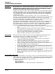
Section 1 Product Safety Information Safety Notice Be sure that you are completely familiar with the safe operation of this equipment. This equipment may be connected to other machines that have rotating parts or parts that are controlled by this equipment. Improper use can cause serious or fatal injury. Always disconnect all electrical loads before starting the generator. Installation and repair procedures require specialized skills with electrical generating equipment and liquid cooled engine systems.
Precaution Statements Used In This Manual There are three classifications of precautionary statements used in this manual. The most critical is a WARNING statement, then the Caution statement and the least critical is the Note statement. The usage of each statement is as follows: WARNING: Indicates a potentially hazardous situation which, if not avoided, could result in injury or death. Caution: Indicates a potentially hazardous situation which, if not avoided, could result in damage to property.
Operation Warning Statements Continued WARNING: Be sure that you understand how to stop the engine quickly in case of an emergency situation. Become familiar with the controls and safety systems provided with this generator set. WARNING: Always wear safety glasses with side shields and hearing protection when working near the generator. WARNING: Improper operation may cause violent motion of connected equipment. Be certain that unexpected movement will not cause injury to personnel or damage to equipment.
Warning Statements Continued Burn WARNING: Parts of this generator are extremely hot during and after operation. To prevent severe burns, do not touch any part of the generator until you have first determined if the part is hot. Wear protective clothing and after use allow sufficient time for parts to cool before touching any part of the generator. WARNING: Do not touch the hot exhaust parts or the high voltage spark plug or coil terminals of the engine.
Warning Statements Continued Maintenance WARNING: Before cleaning, inspecting, repairing, refueling or performing any maintenance to the generator set, always be sure the engine has stopped and that all rotating parts have also stopped. After stopping, certain components are still extremely hot so be careful not to get burned. Before servicing the generator set, be sure to disconnect the spark plug wires and the battery terminals to prevent accidental engine rotation or starting.
Caution Statements Caution: The brass connecting tab on some 120VAC duplex receptacles have been removed. Each receptacle is powered by a separate generator winding. When replacing a receptacle, inspect the brass tab that normally links both receptacles. If it is removed, be sure to remove the brass tab from the replacement receptacle before it is installed. Failure to remove the tab will cause a direct short to the generator windings and cause possible generator damage.
Section 2 General Information This manual contains information you need to safely and efficiently operate your generator set. During the preparation of this manual every effort was made to ensure the accuracy of its contents. This manual describes only very basic engine information. A separate owner’s manual for the engine is supplied with this unit for your use. Please refer to the engine manual for information relative to engine operation, maintenance, recommendations and additional safety warnings.
Limited Warranty Continued Warranty Period Generator Series Labor* Parts Portable Products (Premier, Powerchief, DG Series, K Series) Towable Products (TS) 1 Year 3 Years 1 Year or 3,000 Hours Whichever comes first 1 Year or 1,000 Hours Whichever comes first 1 Year or 3,000 Hours Whichever comes first 1 Year or 1,000 Hours Whichever comes first 1 Year or 1,000 Hours Whichever comes first 1 Year or 1,000 Hours Whichever comes first 3 Years or 3,000 Hours Whichever comes first 3 Years or 1,000 Hours Wh
Section 3 Receiving & Installation Receiving & Inspection When you receive your generator, there are several things you should do immediately. 1. 2. 3. Observe the condition of the shipping container and report any damage immediately to the commercial carrier that delivered your system. Verify that the part number of the system you received is the same as the part number listed on your purchase order.
Physical Location The mounting location of the system is important. It should be installed in an area that is protected from direct harmful gases or liquids, dust, metallic particles, shock and vibration. It can only be installed in an outdoor location so the exhaust fumes are vented to the atmosphere. This system must never be installed inside an enclosed building, home, shop or garage etc. Several other factors should be carefully evaluated when selecting a location for installation: 1.
Electrical Connections Continued Table 3-1 Single Phase Power Receptacle Description Model K3000 K5000 K5000E K6500 K6500E R30 R45/R45E R60/R60E OHV30 OHV50H OHV60/OHV60E OHV85E OHV100E OHV110E Straight 120VAC (20Amp) 2- 5-20R GFCI 120VAC 4- 5-20R GFCI 120VAC 4- 5-20R GFCI 120VAC 4- 5-20R GFCI 120VAC 4- 5-20R GFCI 120VAC 4- 5-20R GFCI 120VAC 4- 5-20R GFCI 120VAC 4- 5-20R GFCI 120VAC 4- 5-20R GFCI 120VAC 4- 5-20R GFCI 120VAC 4- 5-20R GFCI 120VAC 4- 5-20R GFCI 120VAC 4- 5-20R GFCI 120VAC 4- 5-20R GFCI 120VAC
Frame Ground Connection Continued Figure 3-3 Frame Ground Connection Nut Washer Ground Wire Lug Washer Stud Frame Earth Ground Engine Oil Refer to the engine manual that was provided with your generator. Determine the correct type of engine oil and the amount specified by the engine manufacturer. Add the required amount of oil to bring the oil level to full. Battery Connections Applies to 12VDC Electric Start models only. The generator is shipped with no battery installed.
Battery Connections Continued Procedure: The correct type battery must be purchased and installed in the battery compartment provided. 1. Remove the bag containing the battery box components. 2. Set the battery on the battery tray. 3. Install the battery hold down rods as shown in Figure 3-4. a. Place the bent end of the battery hold down rod through the hole in the battery tray. b.
Optional Wheel Kit PDG2 – 2 Wheel Dolly Kit; and PDG4 – 4 Wheel Dolly Kit An optional 2 or 4 wheel dolly kit is available for Premier portable generators. If you have purchased one of these kits, refer to MN2409 for the installation instructions. Recommended Engine Oil and Battery Type Series K MODEL K3000/15.30030 K5000/15.30050 K6500/15.30052 K5000E/15.30051 K6500E/15.30053 SUMMER OIL SAE. 30 SAE. 30 SAE. 30 SAE. 30 SAE. 30 WINTER OIL 5W/30 5W/30 5W/30 5W/30 5W/30 OIL CAPACITY 1.3 PTS 1.75PTS 1.
Section 4 Operation Operator Control Panel Each operator panel is slightly different, depending on features of the generator you purchased. The Operator Control Panel of Figure 4-1 is shown because it has most of the available features. This will be used to explain how the controls operate. Figure 4-1 Operator Control Panel Auto Idler Off – The engine will run continuously at the predetermined speed set by the governor. ON – Allows the engine to run at slow speed when there is no electrical load.
Pre–Start Checks Before the engine is started, several things must first be checked. 1. Place the generator set in an open, dry, well ventilated and reasonably level location. 2. If grounding is required for your application, check to make sure your unit is grounded properly (see Section3). 3. Check the engine’s oil level and add oil if necessary to bring it to the level recommended by the engine manufacturer. 4. Check the fuel level and add fuel to within 1/2 inch of the fill tube if necessary. 5.
Section 5 Troubleshooting and Maintenance Maintenance MN2410 This manual contains only very minimal engine maintenance instructions. Refer to the engine manufacturer’s owner’s manual for specific engine maintenance instructions for your generator set. Any maintenance instructions or recommendations in the engine owner’s manual take precedence over any of the following general recommendations. General: 1. Inspect the fuel system for leaks. Replace all defective components immediately. 2.
Problems and Solutions Some of the more common problems are listed in Table 5-1. This information is intended to be a check or verification that simple causes can be located and fixed. It is not an exhaustive “how to” for all types of problems. Procedures that require in depth knowledge or skills (like flashing the field) should be referred to the Baldor Generator Service Department by calling (920) 236–4200. Table 5-1 Troubleshooting Guide Problem Engine will not start Possible Cause No fuel.
Appendix A Premier K Series Caution: Information in this Appendix applies to the following Baldor Generators: K3000, K5000, K5000E, K6500, K6500E The brass connecting tab on some 120VAC duplex receptacles have been removed. Each receptacle is powered by a separate generator winding. When replacing a receptacle, inspect the brass tab that normally links both receptacles. If it is removed, be sure to remove the brass tab from the replacement receptacle before it is installed.
Replacement Parts Replacement parts assembly views for the Generator set are shown in Figure A-3 and A-4. Parts information is provided in Table A-1. Parts information for the engine is provided in the engine manual that was provided with your generator set. Please refer to the engine manual for replacement parts information.
Table A-1 Generator Set Parts List Continued Ref No. Not Shown Not Shown 13 14 15 16 Not Shown Not Shown Not Shown Not Shown Not Shown Not Shown Not Shown Not Shown Not Shown Not Shown Not Shown Not Shown Not Shown Not Shown Not Shown Not Shown Not Shown Not Shown Not Shown 20 20 21 22 23 Not Shown Not Shown Not Shown Not Shown Not Shown Not Shown Not Shown Not Shown Not Shown Not Shown Not Shown Not Shown Not Shown Not Shown Not Shown Not Shown Not Shown Not Shown Not Shown Part No.
Figure A-5 K3000 Wiring Diagram A-4 Premier K Series MN2410
Figure A-6 K5000 Wiring Diagram MN2410 Premier K Series A-5
Figure A-7 K5000E Wiring Diagram A-6 Premier K Series MN2410
Figure A-8 K6500 Wiring Diagram MN2410 Premier K Series A-7
Figure A-9 K6500E Wiring Diagram A-8 Premier K Series MN2410
Appendix B Premier R Series Information in this Appendix applies to the following Baldor Generators: R30, R45, R45E, R60, R60E Caution: The brass connecting tab on some 120VAC duplex receptacles have been removed. Each receptacle is powered by a separate generator winding. When replacing a receptacle, inspect the brass tab that normally links both receptacles. If it is removed, be sure to remove the brass tab from the replacement receptacle before it is installed.
Replacement Parts Replacement parts assembly views for the Generator set are shown in Figure B-3 and B-4. Parts information is provided in Table B-1. Parts information for the engine is provided in the engine manual that was provided with your generator set. Please refer to the engine manual for replacement parts information. Figure B-3 Alternator Assembly 5 6 10 11 12 ON OFF 15 1 2 13 7 3 14 4 Figure B-4 Frame Assembly 23 21 22 21 20 Table B-1 Generator Set Parts List Ref No.
Table B-1 Generator Set Parts List Continued Ref No. Not Shown 7 10 10 11 12 13 14 15 Not Shown Not Shown Not Shown Not Shown Not Shown Not Shown Not Shown Not Shown Not Shown Not Shown Not Shown 20 20 20 21 22 23 23 Not Shown Not Shown Not Shown Not Shown Not Shown Not Shown Not Shown Not Shown Not Shown Not Shown Not Shown Not Shown Not Shown Part No.
Figure B-5 R30 Wiring Diagram B-4 Premier R Series MN2410
Figure B-6 R45/45E Wiring Diagram MN2410 Premier R Series B-5
Figure B-7 R60 Wiring Diagram B-6 Premier R Series MN2410
LOAD LINE LINE TEST RESET 1430 5110 5100 1120 1130 L530R L1430R NEMA W (SILVER) 30A (GOLD) G X (GOLD) 125/250V X (GOLD) (SILVER) W 1140 1420 5510 1430 5520 ALL WIRES 14 AWG.
B-8 Premier R Series MN2410
Appendix C Premier OHV Series Information in this Appendix applies to the following Baldor Generators: OHV30, OHV50, OHV60, OHV60E, OHV85E Caution: The brass connecting tab on some 120VAC duplex receptacles have been removed. Each receptacle is powered by a separate generator winding. When replacing a receptacle, inspect the brass tab that normally links both receptacles. If it is removed, be sure to remove the brass tab from the replacement receptacle before it is installed.
Replacement Parts Replacement parts assembly views for the Generator set are shown in Figure C-4 and C-5. Parts information is provided in Table C-1. Parts information for the engine is provided in the engine manual that was provided with your generator set. Please refer to the engine manual for replacement parts information.
Table C-1 Generator Set Parts List Continued Ref No. Part No.
Figure C-6 OHV30 Wiring Diagram C-4 Premier OHV Series MN2410
Figure C-7 OHV40 / OHV50 / OHV60 Wiring Diagram MN2410 Premier OHV Series C-5
Figure C-8 OHV60E Wiring Diagram C-6 Premier OHV Series MN2410
Figure C-9 OHV 85E Wiring Diagram MN2410 Premier OHV Series C-7
C-8 Premier OHV Series MN2410
Appendix D Premier OHV100E Series Information in this Appendix applies to the OHV100E Baldor Generator. Caution: The brass connecting tab on some 120VAC duplex receptacles have been removed. Each receptacle is powered by a separate generator winding. When replacing a receptacle, inspect the brass tab that normally links both receptacles. If it is removed, be sure to remove the brass tab from the replacement receptacle before it is installed.
Replacement Parts Replacement parts assembly views for the Generator set are shown in Figure D-2 and D-3. Parts information is provided in Table D-1. Parts information for the engine is provided in the engine manual that was provided with your generator set. Please refer to the engine manual for replacement parts information.
Table D-1 Generator Set Parts List Ref No. 1 2 Not Shown 3 4 Not Shown 5 6 Not Shown Not Shown Not Shown 7 10 11 12 13 14 15 Not Shown Not Shown Not Shown Not Shown 16 Not Shown Not Shown Not Shown Not Shown Not Shown Not Shown Not Shown Not Shown Not Shown Not Shown Not Shown 20 21 22 23 Not Shown Not Shown Not Shown Not Shown Not Shown Not Shown Not Shown Not Shown Not Shown Not Shown Not Shown Not Shown Not Shown Part No.
Figure D-4 OHV100E Wiring Diagram D-4 Premier OHV100E Series MN2410
Figure D-5 OHV100E Generator Output Wiring Diagram MN2410 Premier OHV100E Series D-5
Figure D-6 OHV100E DC Wiring Diagram D-6 Premier OHV100E Series MN2410
Appendix E Premier OHV110E Series Information in this Appendix applies to the OHV110E Baldor Generator. Caution: The brass connecting tab on some 120VAC duplex receptacles have been removed. Each receptacle is powered by a separate generator winding. When replacing a receptacle, inspect the brass tab that normally links both receptacles. If it is removed, be sure to remove the brass tab from the replacement receptacle before it is installed.
Replacement Parts Replacement parts assembly views for the Generator set are shown in Figure E-2 and E-3. Parts information is provided in Table E-1. Parts information for the engine is provided in the engine manual that was provided with your generator set. Please refer to the engine manual for replacement parts information.
Table E-1 Generator Set Parts List Ref No. 1 2 Not Shown 3 4 Not Shown 5 6 Not Shown Not Shown Not Shown 7 10 11 12 13 14 15 Not Shown Not Shown Not Shown Not Shown 16 Not Shown Not Shown Not Shown Not Shown Not Shown Not Shown Not Shown Not Shown Not Shown Not Shown Not Shown 20 21 22 23 Not Shown Not Shown Not Shown Not Shown Not Shown Not Shown Not Shown Not Shown Not Shown Not Shown Not Shown Not Shown Not Shown Not Shown Not Shown Not Shown Part No.
Figure E-4 OHV110E Wiring Diagram E-4 Premier OHV110E Series MN2410
Figure E-5 OHV100E Generator Output Wiring Diagram MN2410 Premier OHV110E Series E-5
Figure E-6 OHV110E DC Wiring Diagram E-6 Premier OHV110E Series MN2410
Baldor District Offices UNITED STATES ARIZONA PHOENIX 4211 S 43RD PLACE PHOENIX, AZ 85040 PHONE: 602-470-0407 FAX: 602-470-0464 CALIFORNIA LOS ANGELES 6480 FLOTILLA COMMERCE, CA 90040 PHONE: 323-724-6771 FAX: 323-721-5859 HAYWARD 21056 FORBES STREET HAYWARD, CA 94545 PHONE: 510-785-9900 FAX: 510-785-9910 COLORADO DENVER 2520 W BARBERRY PLACE DENVER, CO 80204 PHONE: 303-623-0127 FAX: 303-595-3772 CONNECTICUT WALLINGFORD 65 SOUTH TURNPIKE ROAD WALLINGFORD, CT 06492 PHONE: 203-269-1354 FAX: 203-269-5485 FLORID
WARNING: CALIFORNIA PROPOSITION 65 WARNING: Engine exhaust from this product contains chemicals known to the state of California to cause cancer, birth defects and other reproductive harm. WARNING: CALIFORNIA PROPOSITION 65 WARNING: Diesel engine exhaust and some constituents are known to the state of California to cause cancer, birth defects and other reproductive harm.