DSM S--Series Integrated Stepper Motor / Driver Installation Manual 04/07 MN1940
Contents 1 General Information . . . . . . . . . . . . . . . . . . . . . . . . . . . . . . . . . 1-1 2 Introduction . . . . . . . . . . . . . . . . . . . . . . . . . . . . . . . . . . . . . . . . 2-1 2.1 DSM S-Series integrated motor and driver . . . . . . . . . . . . . . . . . 2.1.1 2.2 Receiving and inspection . . . . . . . . . . . . . . . . . . . . . . . . . . . . . . . . 2.2.1 2.3 3 Units and abbreviations . . . . . . . . . . . . . . . . . . . . . . . . . . . . . . . . . . Introduction . . . .
5.2 Baldor SPI Interface . . . . . . . . . . . . . . . . . . . . . . . . . . . . . . . . . . . . . 5.2.1 5.2.2 6 5-4 5-4 5-4 Troubleshooting . . . . . . . . . . . . . . . . . . . . . . . . . . . . . . . . . . . . 6-1 6.1 Introduction . . . . . . . . . . . . . . . . . . . . . . . . . . . . . . . . . . . . . . . . . . . . 6.1.1 6.1.2 6.1.3 6.1.4 7 Starting Baldor SPI Interface . . . . . . . . . . . . . . . . . . . . . . . . . . . . . . . . . . . . . Configuration parameters . . . . . . . . . . . . . .
1 1 www.baldormotion.com General Information LT0227A02 Copyright Baldor (c) 2007. All rights reserved. This manual is copyrighted and all rights are reserved. This document or attached software may not, in whole or in part, be copied or reproduced in any form without the prior written consent of BALDOR. BALDOR makes no representations or warranties with respect to the contents hereof and specifically disclaims any implied warranties of fitness for any particular purpose.
www.baldormotion.com Safety Notice Only qualified personnel should attempt the start-up procedure or troubleshoot this equipment. This equipment may be connected to other machines that have rotating parts or parts that are controlled by this equipment. Improper use can cause serious or fatal injury. Precautions Do not touch any circuit board, power device or electrical connection before you first ensure that no high voltage is present at this equipment or other equipment to which it is WARNING connected.
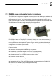
2 2 www.baldormotion.com Introduction 2.1 DSM S-Series integrated motor and driver The DSM S-Series high-torque integrated motor and driver is ideal for designers who want the simplicity of a motor with on-board electronics. The DSM allows the system designer to decide the best method of control. The drive’s integrated electronics eliminates the need to run the motor cabling through the machine, reducing the potential for problems due to electrical noise.
www.baldormotion.com A “Baldor Motion Toolkit CD” is available. This contains the Baldor SPI Interface software, used for communicating and configuring the DSM. This manual is intended to guide you through the installation of the DSM. The chapters should be read in sequence. The Basic Installation section describes the mechanical installation of the DSM.
www.baldormotion.com 2.2 Receiving and inspection When you receive your DSM, there are several things you should do immediately: 1. Check the condition of the packaging and report any damage immediately to the carrier that delivered your DSM. 2. Remove the DSM from the shipping container and remove all packing material. The container and packing materials may be retained for future shipment. 3.
www.baldormotion.com 2.3 Units and abbreviations The following units and abbreviations may appear in this manual: V ............... W .............. A ............... Ω ............... mΩ . . . . . . . . . . . . . μF . . . . . . . . . . . . . . pF . . . . . . . . . . . . . . mH . . . . . . . . . . . . . Volt (also VAC and VDC) Watt Ampere Ohm milliohm microfarad picofarad millihenry Φ............... ms . . . . . . . . . . . . . . μs . . . . . . . . . . . . . . ns . . . . . . . . . . . . . .
3 3 www.baldormotion.com Basic Installation 3.1 Introduction You should read all the sections in Basic Installation. It is important that the correct steps are followed when installing the DSM. This section describes the mechanical installation of the DSM. 3.1.1 Location requirements Ensure you have read and understood the warnings and cautions in section 1. The safe operation of this equipment depends upon its use in the appropriate environment.
www.baldormotion.com 3.1.2 Mounting the DSM Ensure you have read and understood the location requirements in section 3.1.1. Mount the DSM by the four holes in the faceplate. M5 bolts or screws are recommended. 3.1.2.1 Dimensions - DSMS17 Flying leads 305 (12) ‘P’ connector option 11.2 (0.44) All dimensions shown as mm (inches) 30.2 (1.19) 58.3 (2.3) 24 (0.94) 2 (0.08) P1 15 (0.59) Ø5 (0.2) 4 x ØM3x0.5 thread x 3.8 (0.15) deep P2 4.5 (0.18) Ø22 (0.87) 31 (1.22) Square L MAX 42.7 (1.
www.baldormotion.com Maximum length of screw threads into the motor housing is 3.5 mm (0.14 in) Customer’s mounting flange M3 x 0.
www.baldormotion.com 3.1.2.2 Dimensions - DSMS23 Flying leads 305 (12) ‘P’ connector option 11.2 (0.44) All dimensions shown as mm (inches) 51.2 (2.02) 48.3 (1.9) 41.4 (1.63) 20.6 (0.81) P1 Ø6.35 (0.25) 15 (0.59) 75.2 (2.96) 4 x Ø5 (0.2) P2 5.8 (0.23) 4.9 (0.19) 47.14 (1.86) Square L MAX 56.4 (2.22) Square L MAX2 DSMS Model Dimensions (mm / inches) Weight LMAX LMAX2 (with control knob) kg / lb DSMS23x-1B 67.31 (2.65) 85.34 (3.36) 0.61 (1.35) DSMS23x-2B 76.71 (3.02) 94.74 (3.
www.baldormotion.com 3.1.2.3 Dimensions - DSMS34 Flying leads 305 (12) 4 x Ø5.5 (0.22) 37 (1.46) 2 (0.08) 25 (0.98) 13 (0.51) 94.7 (3.73) Ø14 (0.55) 18.6 (0.73) 10 (0.39) Ø73 (2.87) 31.8 (1.25) 86.1 (3.39) L MAX L MAX2 69.6 (2.74) All dimensions shown as mm (inches) Motor Stack Dimensions (mm / inches) Weight LMAX LMAX2 (with control knob) kg / lb 94.2 (3.71) 112.3 (4.42) 1.9 (4.19) DSMS34F-2B 114.3 (4.50) 132.3 (5.21) 2.5 (5.5) DSMS34F-3B 154.2 (6.07) 172.2 (6.78) 4.0 (8.
www.baldormotion.com 3.1.3 Other requirements for installation H The DSM requires a power supply as described in section 4.2.
4 4 www.baldormotion.com Input / Output 4.1 Introduction This section describes the input and output connections of the DSM. Logic level cables must not run parallel to power cables. Power cables will introduce noise into the logic level cables and make the system unreliable. Logic level cables must be shielded to reduce the chance of induced noise. The shield needs to be grounded at the signal source to AC ground; the other end of the shield must not be connected.
www.baldormotion.com 4.2 Motor power input The DSM requires an unregulated DC power supply. The power supply current will depend upon voltage and load, but will not exceed 2 A (DSMS17 / DSMS23) or 4 A (DSMS34).
www.baldormotion.com 4.2.1 Wire sizes Table 1 describes the wire sizes to provide optimal protection against EMI and RFI. Correct wire size is determined by the current requirement and the cable length. The actual cable type, wire gauge, shield type and filtering devices used are dependent on the customer’s application and system. Always use shielded twisted pairs for AC and DC supply cables. For logic wiring (see section 4.3) AWG22 wire is recommended.
www.baldormotion.com 4.3 Logic inputs The DSM has three optically isolated logic inputs. These inputs are isolated to minimize or eliminate electrical noise coupled onto the drive control signals, and are over-voltage protected. The inputs may be configured as either sinking inputs or sourcing inputs (model dependent, see section 4.3.3), with the Optocoupler Reference (white) lead as the reference. This allows the DSM to be interfaced to a variety of controllers.
www.baldormotion.com closed) will cause the driver output circuitry to be disabled. Note that the internal sine/cosine position generator will continue to increment or decrement as long as step clock pulses are being received by the DSM. The enable input is not synchronized to any other input and may be changed at any time. 4.3.2 Input timing The direction input and the microstep resolution inputs are internally synchronized to the positive going edge of the step clock input.
www.baldormotion.com 4.3.3 Sinking / sourcing input configuration All DSMS17, 23 and 34 models can be wired to create sinking inputs, where a reference voltage between +5 and +24 VDC is connected to the Optocoupler Reference (white) lead. The isolated inputs are then interfaced to a sinking output (which utilizes the same supply as the opto coupler reference input) such as a switch, open collector, or PLC output.
www.baldormotion.com NextMove ESB (models NSB003-501 / NSB003-502 only) ‘X2’ +5 V +5 V ULN2003 Step Output Optocoupler reference 4 1k* STEP0 DSM 3 Step clock input 74AHCT244 GND 1k* ULN2003 Direction Output DIR0 5 Direction input 74AHCT244 DGND GND 1 +5 V ‘X12’ REL COM 7 Enable REL NC 8 Enable input Figure 11 - Sourcing input connections from a typical controller (e.g.
www.baldormotion.com 4.4 SPI interface DSM setup parameters are changed via an SPI (Serial Peripheral Interface) port. This port uses a 10-pin IDC header, and connects to a USB port on your PC. The recommended method of connecting the SPI port to the PC is by using parameter setup cable CBL055-501. The PC requires a standard USB port. 4.4.1 SPI connector Location 10-pin IDC header (DSMS17... / DSMS23...) Additional flying leads (DSMS34...
www.baldormotion.com 4.4.2 SPI signal descriptions 4.4.2.1 +5 V out This output is a voltage supply for the setup cable only. It is not designed to power any external devices 4.4.2.2 CLK The clock is driven by the master and regulates the flow of the data bits. The master may transmit data at a variety of baud rates. The clock cycles once for each bit that is transferred. 4.4.2.3 MISO Carries output data from the DSM back to the SPI master. Only one DSM can transmit data during any particular transfer. 4.
www.baldormotion.com 4.5 Connection summary - minimum system wiring As a guide, Figure 13 shows an example of the typical minimum wiring required to operate the DSM in conjunction with a NextMove ESB controller. Motor power supply X12 Red - 12-48 VDC / 12-75 VDC Black - 0 V Ferrite & filter not shown.
5 5 www.baldormotion.com Operation 5.1 Introduction The motor interface is accessed through the Baldor SPI Interface software, which is an easy to install and easy to use program used to set the DSM’s parameters. The Baldor SPI Interface is included on the Baldor Motion Toolkit CD. 5.1.1 Connecting the DSM to the PC The DSM is connected to the PC using a standard USB port. It is recommended to use the optional CBL055-501 parameter setup cable (see section 4.4). 5.1.
www.baldormotion.com 4. When Windows finds the required VCP driver files, a dialog will warn that they have not passed ‘Windows Logo testing’. This is normal for the parameter setup cable’s VCP driver, so click Continue Anyway to continue with the installation. 5. When the Completing the Found New Hardware Wizard message appears, click Finish. A final Found New Hardware message will appear on the task bar to inform you that the hardware is now ready to use.
www.baldormotion.com 5.1.6 Starting the controller and DSM If you have followed the instructions in the previous sections, you should have now connected power sources, inputs and outputs, and the USB cable linking the PC with the DSM. Before you apply power for the first time, it is very important to verify the following: H H H Inspect all power connections for accuracy, workmanship and tightness. Verify that all wiring conforms to applicable codes. Check all signal wiring for accuracy. 1.
www.baldormotion.com 5.2 Baldor SPI Interface The Baldor SPI Interface is a simple application for configuring all aspects of the DSM. 5.2.1 Starting Baldor SPI Interface On the Windows Start menu, select Programs, BALDOR SPI Interface, BALDOR SPI Interface. The software will immediately try to establish communication with the DSM. If this step fails, the word “Disconnected” will appear in red. Check that the DSM is powered and that the cable is connected, then choose the Port menu item.
www.baldormotion.com Microstep Resolution Select (MSEL) The MSEL parameter specifies the microstep resolution of the DSM. The following table lists valid MSEL parameter settings: MSEL value: Steps per revolution MSEL value: Steps per revolution 1 200 64 12800 2 400 100 20000 4 800 108 21600 (1 microstep = 1 arc minute) 5 1000 125 25000 8 1600 127 25400 (1 microstep = 0.001 mm) 10 2000 128 25600 16 3200 180 36000 (1 microstep = 0.
www.baldormotion.com 5.2.2.2 I/O settings view The I/O settings view shows two additional parameters for the DSM: Clock Type The Clock Type parameter configures the step and direction inputs for the type of input signals being supplied to the motor. H Step/Dir is the default setting. A waveform supplied to the step input causes the motor to advance one step for each rising edge. The direction input is held either high or low to determine the direction of motion.
6 6 www.baldormotion.com Troubleshooting 6.1 Introduction This section explains common problems and their solutions. 6.1.1 Problem diagnosis If you have followed all the instructions in this manual in sequence, you should have few problems installing the DSM. If you do have a problem, read this section first. 6.1.2 Further support If you need to contact Baldor technical support by telephone or fax, contact details are provided at the front of this manual.
www.baldormotion.com 6.1.4 Motor control problems Symptom Check Controller outputs appears to be working, but will not cause DSM to turn. Check that the DSM is powered. Check that the logic connections between motor and controller are correct. Confirm that the sense of the enable input is correct to enable the motor (section 4.3.1.3). Controller reports that the DSM is not moving and drops the enable line.
7 www.baldormotion.com Specifications 7 7.1 Introduction This section provides technical specifications of all DSM models. 7.1.1 Input power Description DSMS17... Required supply type DSMS23... DSMS34... Unregulated DC Ripple voltage ±10% Minimum supply voltage +12VDC +12VDC +12VDC Maximum supply voltage +48VDC +75VDC +75VDC Input current (maximum) 2A 1.5A 4A The maximum input voltage of the DSM includes motor back EMF, power supply ripple and high line.
www.baldormotion.com 7.1.2 Motor speed & torque - DSMS17 60 42 50 35 40 28 30 21 20 14 24 VDC 48 VDC 10 0 0 7 1000 2000 3000 4000 5000 6000 7000 (300) (600) (900) (1200) (1500) (1800) (2100) Torque·(N cm) Torque (oz·in) 7.1.2.1 DSMS17x-1A... Speed in full steps per second (RPM) Description Value Holding torque 22.6 N·cm (32 oz·in) Detent torque 1.17 N·cm (1.66 oz·in) Rotor inertia 0.038 kg·cm2 (0.
www.baldormotion.com 60 42 50 35 40 28 30 21 20 14 24 VDC 10 7 48 VDC Torque (N·cm) Torque (oz·in) 7.1.2.3 DSMS17x-3A... 0 0 1000 2000 3000 4000 5000 6000 7000 (300) (600) (900) (1200) (1500) (1800) (2100) Speed in full steps per second (RPM) Description Value Holding torque 52.9 N·cm (74.9 oz·in) Detent torque 2.45 N·cm (3.47 oz·in) Rotor inertia 0.082 kg·cm2 (0.
www.baldormotion.com 7.1.3 Motor speed & torque - DSMS23 7.1.3.1 DSMS23x-1B... 225 159 24 VDC 45 VDC 75 VDC 200 141 124 150 106 125 88 100 71 75 53 50 35 25 18 0 0 1000 2000 (300) (600) 3000 (900) 4000 5000 (1200) 6000 (1500) (1800) Torque (N·cm) Torque (oz·in) 175 7000 (2100) Speed in full steps per second (RPM) Description Value Holding torque 64 N·cm (90 oz·in) Detent torque 2.7 N·cm (3.9 oz·in) Rotor inertia 0.18 kg·cm2 (0.0025 oz·in·s2) 7.1.3.2 DSMS23x-2B...
www.baldormotion.com 7.1.3.3 DSMS23x-3B... 225 159 24 VDC 45 VDC 200 141 124 75 VDC 150 106 125 88 100 71 75 53 50 35 25 18 0 0 1000 2000 3000 4000 5000 6000 7000 (300) (600) (900) (1200) (1500) (1800) (2100) Torque (N·cm) Torque (oz·in) 175 Speed in full steps per second (RPM) Description Value Holding torque 169 N·cm (239 oz·in) Detent torque 6.86 N·cm (9.7 oz·in) Rotor inertia 0.46 kg·cm2 (0.
www.baldormotion.com 7.1.4 Motor speed & torque - DSMS34 7.1.4.1 DSMS34x-1B... 706 1000 900 635 24 VDC 45 VDC 75 VDC 700 465 494 600 423 500 353 400 282 300 211 200 140 100 71 0 0 1000 (300) 2000 (600) 3000 (900) 4000 (1200) 5000 (1500) 6000 (1800) Torque (N·cm) Torque (oz·in) 800 7000 (2100) Speed in full steps per second (RPM) Description Value Holding torque 269 N·cm (381 oz·in) Detent torque 7.7 N·cm (10.9 oz·in) Rotor inertia 1.0 kg·cm2 (0.
www.baldormotion.com 7.1.4.2 DSMS34x-2B... 706 1000 635 900 24 VDC 800 494 75 VDC 600 423 500 353 400 282 300 211 200 140 100 71 0 0 1000 2000 3000 4000 5000 6000 7000 (300) (600) (900) (1200) (1500) (1800) (2100) Torque (N·cm) Torque (oz·in) 465 45 VDC 700 Speed in full steps per second (RPM) Description Holding torque Value 406 N·cm (575 oz·in) Detent torque 10.0 N·cm (14.16 oz·in) Rotor inertia 1.6 kg·cm2 (0.
www.baldormotion.com 7.1.4.3 DSMS34x-3B... 706 1000 635 900 24 VDC 800 494 75 VDC 600 423 500 353 400 282 300 211 200 140 100 71 0 0 1000 2000 3000 4000 5000 6000 7000 (300) (600) (900) (1200) (1500) (1800) (2100) Torque (N·cm) 700 Torque (oz·in) 465 45 VDC Speed in full steps per second (RPM) Description Value Holding torque 749 N·cm (1061 oz·in) Detent torque 14.0 N·cm (19.83 oz·in) Rotor inertia 3.4 kg·cm2 (0.
www.baldormotion.com 7.1.5 Digital inputs Description Unit Type Opto-isolated Supply voltage VDC Maximum Minimum 24 5 Input forward voltage (max) Step clock / Direction Enable VDC Input current (typical, 5V) Step clock / Direction Enable mA Input current (maximum allowable) Step clock / Direction Enable mA Maximum input frequency MN1940 Value 1.7 1.4 10.6 6.7 15 9.4 MHz 2.
www.baldormotion.
Index A D Abbreviations, 2-4 Dimensions DSMS17, 3-2 DSMS23, 3-4 DSMS34, 3-5 DIR (direction override), 5-5 Direction input, 4-4 B Baldor SPI Interface, 5-4 clock IOF, 5-6 clock type, 5-6 configuration parameters, 5-4 DIR (direction override), 5-5 direction override (DIR), 5-5 HCDT (hold current delay time), 5-5 hold current delay time (HCDT), 5-5 MHC (motor holding current), 5-5 microstep resolution select (MSEL), 5-5 motor holding current (MHC), 5-5 motor run current (MRC), 5-5 MRC (motor run current),
M Operation, 5-1 connecting to the PC, 5-1 installing Baldor SPI interface, 5-2 installing the USB driver, 5-1 installing the virtual COM port driver, 5-1 starting, 5-3 Options, availability, 2-2 input power, 7-1 motor output - DSMS17x-1A, 7-2 motor output - DSMS17x-2A, 7-2 motor output - DSMS17x-3A, 7-3 motor output - DSMS23x-1B, 7-4 motor output - DSMS23x-2B, 7-4 motor output - DSMS23x-3B, 7-5 motor output - DSMS34x-1B, 7-6 motor output - DSMS34x-2B, 7-7 motor output - DSMS34x-3B, 7-8 SPI interface, 4-8
Comments If you have any suggestions for improvements to this manual, please let us know. Write your comments in the space provided below, remove this page from the manual and mail it to: Manuals Baldor UK Ltd Mint Motion Centre 6 Bristol Distribution Park Hawkley Drive Bristol BS32 0BF United Kingdom. Alternatively, you can e-mail your comments to: manuals@baldor.co.uk Comment: continued...
Thank you for taking the time to help us.
Baldor UK Ltd Mint Motion Centre 6 Bristol Distribution Park Hawkley Drive, Bristol BS32 0BF United Kingdom Visit www.baldormotion.com/supportme for the latest documentation and software releases.