
Electric Company Stepper Machine User Manual


www.baldormotion.com
Input / Output 4-1MN1940
4.1 Introduction
This section describes the input and output connections of the DSM.
Logic level cables must not run parallel to power cables. Power cables will introduce noise into
the logic level cables and make the system unreliable. Logic level cables must be shielded to
reduce the chance of induced noise. The shield needs to be grounded at the signal source to
AC ground; the other end of the shield must not be connected. This allows the shield to act as
adrain.
Do not connect or disconnect any wiring when power is applied! Disconnect the
AC power side to power down the DC power supply. For battery operated
systems, connect a transient suppressor across the power switch to prevent arcs
and high voltage spikes.
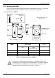
4.1.1 Basic connections
(NC)
SPI interface
Chip Select
Flying
leads
Color Description Pin
White +5 VDC Optocoupler reference 1..
(NC)
Orange Step Clock input 3..... ........
Blue CW/CCW Direction input 4... ....
Brown Enable/Disable input 5.... ......
Black Motor power GND 6..... .......
Red Motor power 7......... ..........
(12-48 VDC or 12-75 VDC)
‘P’ connector
Models with ‘P’
connector option
(DSMS17P... /
DSMS23P... only)
Master Out /
Slave In
(NC)
Master In /
Slave Out
1
3
5
7
9
2
4
6
8
10
(NC)
GND +5 V Out
Clock
(NC)
Figure 5 - Basic connection summary
4 Input / Output
4
CAUTION