Modbus Plus Expansion Board Catalog No.
Table of Contents Section 1 General Information . . . . . . . . . . . . . . . . . . . . . . . . . . . . . Introduction . . . . . . . . . . . . . . . . . . . . . . . . . . . . . . . . . . . . . . . . . Limited Warranty . . . . . . . . . . . . . . . . . . . . . . . . . . . . . . . . . . . . . Safety Notice . . . . . . . . . . . . . . . . . . . . . . . . . . . . . . . . . . . . . . . . Section 2 Expansion Board Description . . . . . . . . . . . . . . . . . . . . Section 3 Installation . . . . . . . . . . . .
ii Table of Contents
Section 1 General Information Introduction The Baldor controls represent the latest technology in microprocessor based motor controls. In addition to the user programmable parameters available in every control, many different expansion boards are available from Baldor to further customize the control to most any application. Expansion boards are categorized by compatibility into two groups: Group 1 and Group 2, see Table 1-1. A board from either group may be used alone in a control.
Limited Warranty For a period of two (2) years from the date of original purchase, BALDOR will repair or replace without charge controls and accessories which our examination proves to be defective in material or workmanship. This warranty is valid if the unit has not been tampered with by unauthorized persons, misused, abused, or improperly installed and has been used in accordance with the instructions and/or ratings supplied.
Safety Notice This equipment contains voltages that may be as great as 1000 volts! Electrical shock can cause serious or fatal injury. Only qualified personnel should attempt the start-up procedure or troubleshoot this equipment. This equipment may be connected to other machines that have rotating parts or parts that are driven by this equipment. Improper use can cause serious or fatal injury. Only qualified personnel should attempt the start-up procedure or troubleshoot this equipment.
WARNING: Be sure the system is properly grounded before applying power. Do not apply AC power before you ensure that all grounding instructions have been followed. Electrical shock can cause serious or fatal injury. WARNING: Do not remove cover for at least five (5) minutes after AC power is disconnected to allow capacitors to discharge. Dangerous voltages are present inside the equipment. Electrical shock can cause serious or fatal injury.
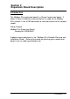
Section 2 Expansion Board Description Introduction The Modbus Plus expansion board is a Group 2 expansion board. It allows a Series H control to communicate as a node on the Modbus Plus network. It has a DB9 connector to make connection to the network simple. Group 2 board Modbus Plus Expansion Board Catalog No. EXB015A01 A good resource document is the “Modicon Plus Network Planning and Installation Guide”. Refer to that guide for planning your network and details such as cable specifications etc.
2-2 Description
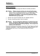
Section 3 Installation Board Installation This section describes the Expansion Board installation procedure. Caution: Before you proceed, be sure to read and become familiar with the safety precautions at the beginning of this manual. Do not proceed if you are unsure of the safety precautions described. If you have any questions, contact BALDOR before you proceed. 1. 2. Remove the expansion board from the shipping container. Remove all packing material from the board.
AC Controls (For all 15H Inverter, 21H Line Regen Inverter, 18H Vector, 22H Line Regen Vector and 23H Servo). Single Expansion Board Installation Procedure: 1. Be sure drive operation is terminated and secured. 2. Remove all power sources from the control. 3. Wait at least 5 minutes for internal capacitors to discharge. 4. Remove the four (4) Phillips head screws (1/4 turn) that secure the control cover. (For A & B size, remove four screws that secure the cover.
AC Controls Single Expansion Board Installation (Continued) Figure 3-1 Single Expansion Board Installation Expansion Board Motor Control Board Terminal tightening torque is 7 lb-in (0.8 Nm) maximum.
AC Controls (Continued) Dual Expansion Board Installation Procedure: 1. Be sure drive operation is terminated and secured. 2. Remove all power sources from the control. 3. Wait at least 5 minutes for internal capacitors to discharge. 4. Remove the four (4) Phillips head screws (1/4 turn) that secure the control cover. (For A & B size, remove four screws that secure the cover. On floor mounted G size enclosures, open the enclosure door). 5. Remove the control cover. 6.
AC Controls Dual Expansion Board Installation (Continued) 12. When complete, install the control cover using the four (4) Phillips head screws (1/4 turn). (For A & B size, install four screws that secure the cover. On floor mounted G size enclosures, close the enclosure door). 13. Restore all power sources to the control. 14. Restore drive operation.
3-6 Installation
Section 4 Hardware Setup A good resource document is the “Modicon Plus Network Planning and Installation Guide”. Refer to that guide for planning your network and details such as cable specifications etc. DIP Switch Settings This procedure will configure the Modbus Plus Expansion Board for communication with a computer or terminal. Reference Figure 4-1 and Table 4-1 for the following procedure. 1. Set DIP switches 1 through 6 for the desired board address. 2.
Figure 4-1 Board Configuration Modbus Plus Expansion Board Catalog No. EXB015A01 D5 D5 Power LED J4 J1 PB1 Reset switch (Processor only) To reset the board, turn control off then on (cycle power). PB1 D2 Error LED D3 Status LED D4 Status LED S1 All switches shown in ON (Down) position.
Table 4-1 Switch Settings Modbus Plus Address 1 2 3 4 5 6 7 8 9 10 11 12 13 14 15 16 17 18 19 20 21 22 23 24 25 26 27 28 29 30 31 32 33 ... 63 1 0 1 0 1 0 1 0 1 0 1 0 1 0 1 0 1 0 1 0 1 0 1 0 1 0 1 0 1 0 1 0 1 0 ... 1 2 0 0 1 1 0 0 1 1 0 0 1 1 0 0 1 1 0 0 1 1 0 0 1 1 0 0 1 1 0 0 1 1 0 ...
LED Indicators Five LED’s are located on the Modbus Plus expansion board (see Figure 4-1 for their locations). D1 Modbus Plus Status LED D1 displays the operational status of the Modbus Plus Interface expansion board (EXB). When power is first applied, the LED will pause, then flash slowly 8 times while it checks the network. If a valid Modbus Plus connection is established, D1 will flash continuously. Otherwise, it flash an error code as shown in Table 4-2.
Control Terminal Strip Connections For Serial Mode operation, the Input/Output terminal strip of the control (J1 of the Vector and DC controls and J4 of the Inverters) is wired as shown in Figure 4-2. Connect the Enable, Forward Enable Switch, Reverse Enable Switch, External Trip and Opto Common connections as shown. Note: All opto-isolated outputs and analog outputs remain active while operating in the Serial Mode.
4-6 Hardware Setup
Section 5 Register Map for Modbus Plus Configure Control Software for Modbus Plus Mode The Series H control operating mode must be set to Serial to use the Modbus Plus expansion board. There is no selection for Modbus Plus on the Level 1 Input block Operating mode parameter list. However, selecting Serial with the Modbus Plus expansion board installed will allow operation of the Modbus Plus board.
Action Press Y or B key Press Enter key Press Y key Press Enter key Press Y or B key Press Enter key Press Y or B key Press ENTER key Press Y or B key Press ENTER key Press Enter key Press Y or B key Press ENTER key Press Y or B key Press DISP key Press LOCAL key Description Scroll to Serial mode Display OPERATING MODE SERIAL Saves mode change value OPERATING MODE P: SERIAL Scroll to Command Select parameter Flashing cursor indicates mode can be changed Scroll to Serial mode COMMAND SELECT P: +/–10VOL
Data Exchange with the Modbus Plus Expansion Board This section describes the register interface used for data exchange with the Series H control. Motor drive parameters are mapped to Modbus Plus “Data/Holding” registers (4xxxx). Parameters can be read from or written to the Series H control by reading from or writing to the appropriate Modbus Plus registers.
For 15Hand 21H Inverter controls, use the following registers for communication. For all other H controls, use the Standard Series H Area Register Mapping. Series 15H Specific Area Register Mapping Register Address T# Read/Write 47000 31 Read Only Terminal Strip (see NOTE 1) 47001 45 Read Only Fault Status (0=no fault present) 47002 17 Read Only Current Actual (100mA RMS) 47003 18 Read Only Speed Actual (RPM) 47004 19 Read Only Frequency Actual (.
Standard Series H Area Register Mapping (except 15H and 21H controls) Register Address T# Read/Write Description 48000 17 Read Only Current Actual (100mA RMS) 48001 18 Read Only Speed Actual (RPM) 48002 19 Read Only Frequency Actual (.
Standard Series H Area Register Mapping Continued Register Address T# Read/Write 48100 6 Read/Write Hz Speed Ref 48101 7 Read/Write Speed Ref (RPM) 48102 8 Read/Write Speed Ref (High resolution – 1/256 RPM) (low order) 48103 8 Read/Write Speed Ref (High resolution – 1/256 RPM) (high order) 48104 9 Read/Write Torque Ref (±15 bits = programmed current limit) 48105 10 Read/Write Process Ref (±14 bits = full scale) 48106 11 Read/Write Process Feedback (±14 bits = full scale) 48107
Standard Series H Area Register Mapping Continued Register Address T# Read/Write 49000 1 Read/Write Run Cmd (0=stop, 1=fwd, 2=rev, 3=bipolar) 49001 2 Write Only Run Inhibit (1=stop, regardless of Control Source) 49002 3 Read/Write Control Source (0=keypad,1=terminal strip,2=network) 49003 5 Read/Write Command Mode (see NOTE 2) 49004 4 Read Only Control State (0=not ready, 1=ready, 2=enabled, 3=stopping, 4=faulted 49005 45 Read Only Fault Status (0=no fault present) 49006 46 Wr
Note 1: Terminal Strip Series 18H, 22H and 23H Controls Bit Name Terminal Number Series 15H and 21H Controls Name Terminal Number 15 Not Used Not Used 14 Not Used Not Used 13 Not Used Not Used 12 Input 1 J1–8 Input 1 J4–8 11 Input 2 J1–9 Input 2 J4–9 10 Input 3 J1–10 Input 3 J4–10 9 Input 4 J1–11 Input 4 J4–11 8 Input 5 J1–12 Input 5 J4–12 7 Input 6 J1–13 Input 6 J4–13 6 Input 7 J1–14 Input 7 J4–14 5 Input 8 J1–15 Input 8 J4–15 4 Input 9 J1–16 Input 9
Note 2: Command Mode Table Cmd Mode Class Description 0 None All 1 Torque CMD selected source S, V 2 Torque CMD network S, V Closes the current loop with command input from the Torque Ref. register. 3 Speed CMD selected source All Closes the velocity loop with command input from the source selected in the COMMAND SELECT parameter. 4 Speed CMD network All Closes the velocity loop with command input from the Speed Ref. register. 5 Orient S, V* C or Index channel orient.
Class The class field indicates the product classes that support the transaction. The product codes are as follows: E = Encoderless Vector I = Inverter S = Servo V = Vector V* = Vector with custom software for positioning Note 3: Network Watchdog Timer The network watchdog timer is used by the drive to detect a communications loss. Normally, this functions as follows: On initialization/power up, the Watchdog Time = 0 (disabled). If any value other than 0 is written to the Watchdog Time, the timer activates.
H Series – Fault Message Description Fault Code Fault Message Line Regen Fault Description 15H 18H 1 1 Fault in Line REGEN converter unit Series 21H Line REGEN Inverter control. 2 Loss of encoder feedback. Feedback Fault Invalid Base ID 3 3 Failed to read configuration from the Power Base ID value in software. Low INIT Bus V 4 4 Low bus voltage detected on start–up. Regen Res Power 5 5 Excessive power dissipation required by Dynamic Brake Hardware.
H Series – Fault Message Description Continued Fault Code Fault Message µp Reset 18H 22 22 A software watchdog timer has reset the processor because a process has timed out. 23 ROM checksum error. 24 Peak output current exceeded the 1 minute rating value. ROM Fault 1 Min Overload Fault Description 15H 24 No I Feedback 25 Loss of current feedback New Base ID 26 26 Control board detected a change in the Power Base ID value in software.
BALDOR ELECTRIC COMPANY P.O.