
User manual

Modbus RTU 7MN744
Control Modes
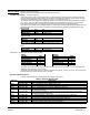
Digital inputs used in all control modes supported in H2 drives are described in Table 5.
Pre-Conditions: Before a H2 drive can be placed in any of the control modes through Modbus application layer
following operating conditions have to be met:
S Drive is disabled (J2- 8 is open)
S Operating Mode parameter (P1401) is set to NETWORK or MINT operating mode.
Note: MINT-operating mode can only be chosen when a Mint Expansion Board is installed in the H2 drive.
Mode Control is set to REMOTE as indicated by LOC/REM STATUS parameter (P2).
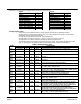
Table 5 Digital Inputs Used in Control Modes
Digital Input Name State Action
J2-8 ENABLE
OFF PWM's will be turned off. FWD and REV hardware limits will be ignored. All commands will be ignored.
ON PWM's will be enabled. Motion status will depend up on FWD, REV hardware limits.
J2-9 FWD LIMIT
OFF FORWARD Motion will be inhibited. Treated as hard limit.
ON FORWARD Motion will be enabled. Treated as hard limit.
J2-10 REV LIMIT
OFF REVERSE Motion will be inhibited. Treated as hard limit.
ON REVERSE Motion will be enabled. Treated as hard limit.
J2-16
EXTERNAL
TRIP
OFF No Action
ON External Fault Active. PWM's will be turned off. FWD and REV hardware limits will be ignored.
All commands will be ignored.
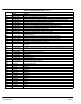
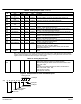
Table 6 Control Modes Description
Control Mode Action Control Sources/Commands
NULL MODE
Turns off PWM's to the
inverter gates regardless of
run command condition.
Writing `1' to this coil clears
all control mode coils and
latches (sets) the NULL
MODE coil.
Ignored
TORQUE MODE
Torque control mode is similar
to BIPOLAR operating mode.
Closes the current (torque)
loop with command input from
the source selected in the
“Command Source”
parameter (P1402)
Writing `1' to this coil will latch
(set) the `TORQUE MODE'
coil and will clear all other
control mode coils.
NOTE: Applicable only in
Vector/Servo product variants.
Writing'0' to this coil will clear
the “TORQUE MODE” coil if
it's already SET or else it will
be ignored.
Control Source.2 NETWORK: when set to `1' replaces the command source selection to
“NETWORK”. Same as setting P1402 to “NETWORK”.
Control Command.13: STOP COMMAND. Writing `1' will issue stop command to the drive.
Drive will switch to speed mode with current speed as initial seed to the ramp generator
and DECEL TIME#1 as the ramp limit. Will hold zero speed unless J2-8, J2-9 or J2-10
is open.
Control Command.17: DRIVE ENABLE. Writing `1' will enable the drive provided J2-8 is
closed. Writing `0' will issue a disable command to the drive and PWM's will be turned
off and all other control commands will be ignored till this coil is set again.
Control Command.14: FORWARD COMMAND. Writing `1' will enable the forward motion
provided J2-8 and J2-9 are closed. Writing `0'will issue a STOP command to the drive.
Control Command.15: REVERSE COMMAND. Writing `1' will enable the reverse motion
provided J2-8 and J2-10 are closed. Writing `0'will issue a STOP command to the
drive.
Control Command.16: BIPOLAR COMMAND. Writing `1' will enable the forward/reverse
motion provided J2-8, J2-9 and J2-10 are closed. Writing `0'will issue a STOP
command to the drive. Actual direction of motion will depend on the polarity of torque
command. Useful while implementing 3-wire modes.
Command Source: P1402. determines the source of torque reference. It could be set of
any of the 8 selections except “NONE” or “KEYPAD”. If command source is set to
“NETWORK” then “TORQUE REFERENCE” holding register (Modbus Reference
40017/18) will become the torque reference source.
ORIENTATION MODE
Orient/Homing control mode
using the Index or external
homing marker signal. Motor
will be commanded in the
forward direction at “HOMING
SPEED” (as set by P2305)
until the index or homing
marker is detected. Drive will
hold this position or at an
offset (as set by P2306) of
“HOMING OFFSET” from this
position.
Writing `1' to this coil will
initiate the `ORIENTATION
MODE'.
Writing `0' will abort the
`ORIENTATION MODE' if it's
already in progress or else it
will be ignored.
NOTE: Applicable only in
Vector/Servo product variants.
Only accel group 1 is used for homing.
Control Command.17: DRIVE ENABLE. Writing `1' will enable the drive provided J2-8 is
closed. Writing `0' will issue a disable command to the drive and PWM's will be turned
off and all other control commands will be ignored till this coil is set again.
J2-9 and J2-10 hardware limits must be closed for this mode to work correctly.
Homing Speed: P2305. Determines the speed at which search for marker is performed.
Homing Offset: P2306. Determines the final homing position. Offset will be added to the
position captured at the time of detecting the orientation marker.