
User manual

8 Modbus RTU MN744
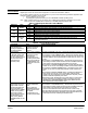
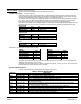
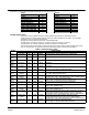
Table 6 Control Modes Description Continued
Control Mode Action Control Sources/Commands
SPEED MODE
Speed control mode is similar
to BIPOLAR operating mode.
Closes the speed loop with
command input from the
source selected in the
“Command Source”
parameter (P1402)
Writing `1' to this coil will latch
(set) the `SPEED MODE' coil
and will clear all other control
mode coils.
NOTE: Applicable only in
Vector/Servo product variants.
Writing'0' to this coil will clear
the “SPEED MODE” coil if it's
already SET or else it will be
ignored.
Control Source.2 NETWORK: when set to `1' replaces the command source selection to
“NETWORK”. Same as setting P1402 to “NETWORK”.Control Source.9: ACC/DEC
Group 1. Selects the accel/decel group 1 for ramp generation.
Control Source.10: ACC/DEC Group 2. Selects the accel/decel group 2 for ramp
generation.
Control Command.13: STOP COMMAND. Writing `1' will issue stop command (sets the
internal speed reference to zero) to the drive. Will hold zero speed unless J2-8, J2-9
or J2-10 is open.
Control Command.17: DRIVE ENABLE. Writing `1' will enable the drive provided J2-8 is
closed. Writing `0' will issue a disable command to the drive and PWM's will be turned
off and all other control commands will be ignored till this coil is set again.
Control Command.14: FORWARD COMMAND. Writing `1' will enable the forward motion
provided J2-8 and J2-9 are closed. Writing `0'will issue a STOP command to the drive.
Control Command.15: REVERSE COMMAND. Writing `1' will enable the reverse motion
provided J2-8 and J2-10 are closed. Writing `0'will issue a STOP command to the
drive.
Control Command.16: BIPOLAR COMMAND. Writing `1' will enable the forward/reverse
motion provided J2-8, J2-9 and J2-10 are closed. Writing `0'will issue a STOP
command to the drive. Actual direction of motion will depend on the polarity of torque
command. Useful while implementing 3-wire modes.
Command Source: P1402. Determines the source of torque reference. It could be set of
any of the 8 selections except “NONE” or “KEYPAD”. If command source is set to
“NETWORK” then “Hz SPEED REFERENCE” holding register (Modbus Reference
40013/14) or “RPM SPEED REFERENCE” holding register (Modbus Reference
40015/16) will become the speed reference source.
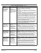
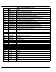
POSITION CMD ABS MODE
Position control mode using
the absolute position
command from the Position
Reference register (Modbus
Ref 40011/12).
Writing `1' to this coil will
initiate the `POSITION CMD
ABS MODE'.
Writing `0' will abort the
`POSITION CMD ABS MODE'
if it's already in progress or
else it will be ignored.
NOTE: Applicable only in
Vector/Servo product variants.
Control Source.9: ACC/DEC Group 1. Selects the accel/decel group 1 for ramp generation.
Control Source.10: ACC/DEC Group 2. Selects the accel/decel group 2 for ramp
generation.
Control Command.17: DRIVE ENABLE. Writing `1' will enable the drive provided J2-8 is
closed. Writing `0' will issue a disable command to the drive and PWM's will be turned
off and all other control commands will be ignored till this coil is set again.
J2-9 and J2-10 hardware limits must be closed for this mode to work correctly.
Position Reference holding register (40011/12) sets the absolute position reference.
Position Speed holding register (40025/26) sets the operating speed during positional
moves.
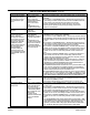
POSITION CMD INC MODE
Position control mode using
the incremental position
command from the Position
Reference register (Modbus
Ref 40011/12).
Writing `1' to this coil will
initiate the `POSITION CMD
INC MODE'.
Writing `0' will abort the
`POSITION CMD INC MODE'
if it's already in progress or
else it will be ignored.
NOTE: Applicable only in
Vector/Servo product variants.
Control Source.9: ACC/DEC Group 1. Selects the accel/decel group 1 for ramp generation.
Control Source.10: ACC/DEC Group 2. Selects the accel/decel group 2 for ramp
generation.
Control Command.17: DRIVE ENABLE. Writing `1' will enable the drive provided J2-8 is
closed. Writing `0' will issue a disable command to the drive and PWM's will be turned
off and all other control commands will be ignored till this coil is set again.
J2-9 and J2-10 hardware limits must be closed for this mode to work correctly.
Position Reference holding register (40011/12) sets the new position reference.
Position Speed holding register (40025/26) sets the operating speed during positional
moves.
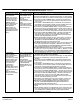
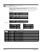
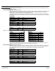
POSITION TRACKING MODE
Positioning mode using the
profiled position (position vs.
time) tracking. Initial
command is given in the
Position Reference register
(Modbus Ref 40011/12).
Writing `1' to this coil will
initiate the `POSITION
TRACKING MODE'.
Writing `0' will abort the
`POSITION TRACKING
MODE' if it's already in
progress or else it will be
ignored.
NOTE: Applicable only in
Vector/Servo product variants.
Control Source.9: ACC/DEC Group 1. Selects the accel/decel group 1 for ramp generation.
Control Source.10: ACC/DEC Group 2. Selects the accel/decel group 2 for ramp
generation.
Control Command.17: DRIVE ENABLE. Writing `1' will enable the drive provided J2-8 is
closed. Writing `0' will issue a disable command to the drive and PWM's will be turned
off and all other control commands will be ignored till this coil is set again.
J2-9 and J2-10 hardware limits must be closed for this mode to work correctly.
Position Reference holding register (40011/12) sets the new position reference.
Position Speed holding register (40025/26) sets the operating speed during positional
moves.
Position FeedForward Tracking Velocity holding register (40027/28) sets the optional
feedforward speed to reduce positioning error during tracked positional moves.