Brushless Servo Motors Installation and Operating Manual 6/06 MN1240
Table of Contents Section 1 General Information . . . . . . . . . . . . . . . . . . . . . . . . . . . . . . . . . . . . . . . . . . . . . . . . . . . Overview . . . . . . . . . . . . . . . . . . . . . . . . . . . . . . . . . . . . . . . . . . . . . . . . . . . . . . . . . Limited Warranty . . . . . . . . . . . . . . . . . . . . . . . . . . . . . . . . . . . . . . . . . . . . . . . . . . Safety Notice . . . . . . . . . . . . . . . . . . . . . . . . . . . . . . . . . . . . . . . . . . . . . . . . . . . . .
ii Table of Contents MN1240
Section 1 General Information Overview This manual contains general procedures that apply to Baldor Motor products. Important: Be sure to read and understand the Safety Notice statements in this manual. For your protection, do not install, operate or attempt to perform maintenance procedures until you understand the Warning and Caution statements. A Warning statement indicates a possible unsafe condition that can cause harm to personnel.
4. 5. 6. 7. Baldor Authorized Service Centers, when convinced to their satisfaction that a Baldor motor developed defects in material or workmanship within the warranty period, are authorized to proceed with the required repairs to fulfill Baldor’s warranty when the cost of such repairs to be paid by Baldor does not exceed Baldor’s warranty repair allowance. Baldor will not pay overtime premium repair charges without prior written authorization.
WARNING: The holding brake alone does not guaranty personnel safety. Use structural measures such as protective fences or a second brake to secure personnel safety. WARNING: This equipment may be connected to other machinery that has rotating parts or parts that are driven by this equipment. Improper use can cause serious or fatal injury. Only qualified personnel should attempt to install operate or maintain this equipment. WARNING: Do not by-pass or disable protective devices or safety guards.
Safety Notice Continued Caution: To prevent premature equipment failure or damage, only qualified maintenance personnel should perform maintenance. Caution: Do not lift the motor and its driven load by the motor lifting hardware. The motor lifting hardware is adequate for lifting only the motor. Disconnect the load from the motor shaft before moving the motor. Caution: To prevent equipment damage, be sure that the control is fused for the maximum motor rated amps listed on the rating plate.
Section 2 Installation Overview Installation should conform to the National Electrical Code as well as local codes and practices. When other devices are coupled to the motor shaft, be sure to install protective devices to prevent accidents. Some protective devices include, coupling, belt guard, chain guard, shaft covers etc. These protect against accidental contact with moving parts.
Receiving Each Baldor Electric Motor is thoroughly tested at the factory and carefully packaged for shipment. When you receive your motor, there are several things you should do immediately. 1. Observe the condition of the shipping container and report any damage immediately to the commercial carrier that delivered your motor. 2. Verify that the part number of the motor you received is the same as the part number listed on your purchase order.
Shaft Loads The motors can be damaged by excessive shaft loads. This may shorten the motor’s service life. The motor warranty is also voided for excessive shaft load related failures. The maximum allowable radial force ( F radial max ) depends on the shaft load. It is determined by (distance x force) and the output shaft design (plain shaft or shaft with keyway). When motor shaft has both a radial load and an axial load, axial load rating = 44% of radial load rating listed.
Figure 2-2 Radial Load Capacity Continued 2-4 Installation MN1240
Life Determination How Life is Determined A life estimate is a calculated, statistical expectancy and is defined as the length of time, or the number of revolutions, until fatigue develops. This life depends on many different factors such as loading, speed, lubrication, operating temperature, contamination, plus other environmental factors. It’s impossible to predict precisely. Statistical calculation estimates are based upon L10 life.
Example:. Provide an estimate L10 life for a BSM90 motor with a radial load or force of 130 lbs (570 N) located 3” (76mm) from the bearing. Operating speed is 1000 RPM. 1. Determine the systems capacity − at the distance for our application. To do this, refer to Figure 2-4 and read information from the curve: a. Locate our distance (3”) on the X axis. b. Pick a speed (8,000 RPM) and locate the intersect with the 3”. c. Read the force (100 lbs) on the Y axis.
Speed and Torque The speed−torque curves for a motor show the safe operating area, speed limit area and intermittent operating area. These curves are used to determine the maximum useable speeds with known torque requirements. If operating within the continuous area, the motor’s thermal limit will not be exceeded. If operated within the intermittent area (extended operation in this area will cause the motor to overheat), the operating time in this area must be limited to prevent overheating.
Motor Code BSM50N−1 BSM50N−2 BSM50N−3 BSM63N−1 BSM63N−2 BSM63N−3 BSM80N−1 BSM80N−2 BSM80N−3 BSM90N−1 BSM90N−2 BSM90N−3 BSM100N−1 BSM100N−2 BSM100N−3 BSM100N−4 BSM80C−1 BSM80C−2 BSM80C−3 BSM90C−1 BSM90C−2 BSM90C−3 BSM100C−1 BSM100C−2 BSM100C−3 BSM100C−4 BSM100C−5 BSM100C−6 2-8 Installation Table 2-1 Brake Specifications Brake Holding Brake Brake Torque Voltage Current Watts (lb−in / N−m) VDC AMPS 13/1.4 10.1 24 0.5 13/1.4 10.1 24 0.5 13/1.4 10.1 24 0.5 18/2 11.9 24 0.6 18/2 11.9 24 0.6 18/2 11.9 24 0.
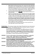
Electrical Connections Overview Figure 2-6 shows typical connections to a control. Note all wiring should be 600volts. Figure 2-6 Typical Connections to Motor Control Motor Temperature Switch Motor Temperature Input Holding Brake Holding Brake Connector Shielded Twisted Pair Wire Motor Ground Wire Motor Connector Shielded Motor Cable V W U G Feedback Connector AC Motor Feedback Control Motor Shielded Twisted Pair Wire All wiring should have 600V rated insulation.
Strain Relief (Mounted at Terminal Box) The motor cable is terminated at the Terminal Box using a Shielded Strain Relief Connector. Figure 2-8 shows the components. 1. Strip the outer shield from the cable to expose the conductors and shield. 2. Slip the Strain Relief components onto the cable in the order shown. 3. Fold the Shield wires over the end of the Contact Carrier. 4. Slide the Threaded Adapter onto the Contact Carrier until the Carrier is completely inserted into the Adapter. 5.
Feedback Termination Connections for Feedback cables are different for each type of feedback device. Standard devices are: Resolver, Halls (Hall Effect), Incremental Encoder with Halls, Absolute Encoder, and SSI (Serial Synchronous Interface) encoder. Custom feedback devices are also available. Request a drawing of your feedback device to determine the pin−out and/or wire color codes.
Feedback Devices Resolver Common feedback devices for Baldor BSM servo motors include Resolver, Encoder, Absolute Encoder, and SSI (Serial Synchronous Interface) encoder. Custom feedback devices are also available. Contact Baldor for more information.
Feedback Devices Continued Encoder Line Count Depends on unit ordered. Standards are 1000−2500 ppr. (Custom resolutions are available.) Supply Voltage 5VDC Supply Current 250mA maximum Output TTL (Line Driver) Figure 2-11 Typical Encoder Feedback Device T a b c a.b.c.
Brushless Servo Motor Identification SS = Stainless Steel IEC 50 63 80 90 100 NEMA 5N 6N 8N 9N C N 1 2 3 4 50 75 etc.
Baldor District Offices
BALDOR ELECTRIC COMPANY 5711 R.S. Boreham Jr.