
Instruction manual


MN1240 Installation 2-11
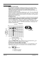
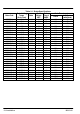
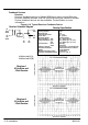
Feedback Termination
Connections for Feedback cables are different for each type of feedback device.
Standard devices are: Resolver, Halls (Hall Effect), Incremental Encoder with
Halls, Absolute Encoder, and SSI (Serial Synchronous Interface) encoder.
Custom feedback devices are also available. Request a drawing of your
feedback device to determine the pin−out and/or wire color codes.
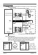
Figure 2-9 Typical Connections to Feedback Termination
Encoder with Halls
Resolver
Function Pin
R1 REF HI 1
R2 REF LO 2
S1 COS+ 3
S3 COS− 4
S2 SINE+ 5
S4 SINE− 6
Open 7−12
Function Pin
DC +5V 1
Ground 2
Channel A+ 3
Channel A− 4
Channel B+ 5
Channel B− 6
Channel C+ 7
Channel C− 8
Open 9
Channel U+ 10
Channel U− 11
Channel V+ 12
Channel V− 13
Channel W+ 14
Channel W− 15
Open 16
8
9
1
712
10
2
6
11
3
5
4
12 Pin
8
9
1
7
12
10
2
6
11
3
5
4
13
14
15
16
16 Pin
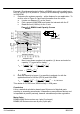
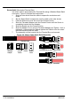
Function Pin
Data− 1
SIN A+ 2
0V Sensor 3
COS B+ 4
Clock− 5
5V Sensor 6
Clock+ 7
COS B− 8
+5V 9
D GND 10
SIN A− 11
Data+ 12
8
9
1
712
10
2
6
11
3
5
4
12 Pin
8
9
1
712
10
2
6
11
3
54
12 Pin
Function Pin
+Vs (5VDC) 1
0V 2
SSI Clock 3
NSSI Clock 4
SSI Data 5
NSSI Data 6
Absolute Encoder
Serial Synchronous Interface
For complete control connections/wiring refer to the following manuals:
MN723 − SD23H MN7423 − H2 Servo
MN1902 − Flex/Flex+Drive
II
MN1901 − MintDrive
II
MN1919 − MicroFlex