PC32Ri and PC43Ri Portable Generator Installation & Operating Manual 5/05 MN2403
WARNING: CALIFORNIA PROPOSITION 65 WARNING: Engine exhaust from this product contains chemicals known to the state of California to cause cancer, birth defects and other reproductive harm. WARNING: CALIFORNIA PROPOSITION 65 WARNING: Battery posts, terminals and related accessories are known to the state of California to cause cancer, birth defects and other reproductive harm.
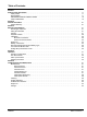
Table of Contents Section 1 Product Safety Information . . . . . . . . . . . . . . . . . . . . . . . . . . . . . . . . . . . . . . . . . . . . . . . . . . . . . . . . . . . . . . . . . . . . . . . . Safety Notice . . . . . . . . . . . . . . . . . . . . . . . . . . . . . . . . . . . . . . . . . . . . . . . . . . . . . . . . . . . . . . . . . . . . . . . . . . . . . . . . . . Responsibility . . . . . . . . . . . . . . . . . . . . . . . . . . . . . . . . . . . . . . . . . . . . . . . . . . . . . . . . . . . .
ii Table of Contents MN2403
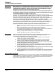
Section 1 Product Safety Information Safety Notice Be sure that you are completely familiar with the safe operation of this equipment. This equipment may be connected to other machines that have rotating parts or parts that are controlled by this equipment. Improper use can cause serious or fatal injury. Always disconnect all electrical loads before starting the generator. Installation and repair procedures require specialized skills with electrical generating equipment.
Symbols This symbol is shown throughout the manual to indicate a connection to ground reference point. Indicates a potentially hazardous situation which, if not avoided, could result in injury or death. Indicates a potentially hazardous situation which, if not avoided, could result in injury or death. Precaution Statements Used In This Manual There are three classifications of precautionary statements used in this manual.
Operation Warning Statements Continued WARNING: Some parts of this generator rotate during operation. Rotating parts can present extreme danger if clothing or body extremities are caught by the rotating part and can cause serious or fatal injury. Never touch a part of the generator until the engine has been stopped and all rotating parts are completely stopped. Also, disconnect the spark plug wires and battery connection to prevent accidental engine rotation during servicing.
Warning Statements Continued Burn WARNING: Parts of this generator are extremely hot during and after operation. To prevent severe burns, do not touch any part of the generator until you have first determined if the part is hot. Wear protective clothing and after use allow sufficient time for parts to cool before touching any part of the generator. WARNING: Do not touch the hot exhaust parts or the high voltage spark plug or coil terminals of the engine.
Warning Statements Continued Maintenance WARNING: Installation and servicing of batteries is to be performed or supervised by personnel knowledgeable of batteries and the required precautions. Keep unauthorized personnel away from batteries. WARNING: Disconnect the battery’s ground terminal before working in the vicinity of the battery or battery wires. Contact with the battery can result in electrical shock when a tool accidently touches the positive battery terminal or wire.
Caution Statements Caution: The brass connecting tab on some 120VAC duplex receptacles have been removed. Each receptacle is powered by a separate generator winding. When replacing a receptacle, inspect the brass tab that normally links both receptacles. If it is removed, be sure to remove the brass tab from the replacement receptacle before it is installed. Failure to remove the tab will cause a direct short to the generator windings and cause possible generator damage.
Section 2 General Information Thank you for purchasing your Baldor Generator Set. This manual contains information you need to safely and efficiently install and operate your generator set. During the preparation of this manual every effort was made to ensure the accuracy of its contents. This manual describes only very basic engine information. A separate owner’s manual for the engine is supplied with this unit for your use.
2-2 General Information MN2403
Section 3 Receiving & Installation Receiving & Inspection When you receive your generator, there are several things you should do immediately. 1. Observe the condition of the shipping container and report any damage immediately to the commercial carrier that delivered your system. Verify that the part number of the system you received is the same as the part number listed on your purchase order.
Physical Location Your generator is portable to go where the work is. To be safe, several factors must be considered: 1. Keep extension cords as short as possible. 2. For effective cooling and maintenance, the generator should be mounted on a flat, smooth, non-flammable level surface. A concrete pad is ideal and provides a secure installation. 3. The location for the generator must be dry. Never operate a generator in an area that has standing water or puddles. 4.
Frame Ground Connection WARNING: Be sure the system is properly grounded before applying power. Do not apply AC power before you ensure that grounds are connected. Electrical shock can cause serious or fatal injury. NEC requires that the frame and exposed conductive surfaces (metal parts) be connected to an approved earth ground. Local codes may also require proper grounding of generator systems.
Battery Connections The generator is shipped with no battery installed. WARNING: Installation and servicing of batteries is to be performed or supervised by personnel knowledgeable of batteries and the required precautions. Keep unauthorized personnel away from batteries. WARNING: Disconnect the battery’s ground terminal before working in the vicinity of the battery or battery wires. Contact with the battery can result in electrical shock when a tool accidently touches the positive battery terminal or wire.
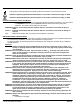
Figure 3-3 Battery Installation Battery Band Battery Base Bolt Flange Bolt Nut Red Cable Flange Bolt Maximum Height: PC32Ri = 5.2 in (131mm) PC43Ri = 6.4 in (162mm) Maximum Width: PC32Ri = 4.5 in (114mm) PC43Ri = 5.4 in (136mm) 5. 6. 7. Maximum Depth: PC32Ri = 2.8 in (71mm) PC43Ri = 3.2 in (82mm) Secure the battery in position using the Battery Band shown in Figure 3-3. Do not lay tools or metal parts on top of batteries.
Voltage Drop in Extension Cords When a long electric extension cord is used to connect an appliance or tool to the generator, a certain amount of voltage drop or loss occurs in the extension cord which reduces the effective voltage available for the appliance or tool. Table 3-2 illustrates the approximate voltage loss when an extension cord of 300 feet (approx. 100 meters) is used to connect an appliance or tool to the generator. Table 3-2 Voltage Drop in Electrical Extension Cords Nominal cross section A.
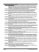
Section 4 Operation Operator Control Panel The Operator Control Panel is shown in Figure 4-1. Figure 4-1 Operator Control Panel Oil Level Lamp Auto Power Save Switch Multi Monitor Display Units LED’s ~ AC OUTPUT Units Select Switch STOP NEMA 5−20R STOP DC Breaker NEMA L530R ON ON START − + − CHOKE + BATTERY CHARGE ONLY DC 12V − 8.
Operator Control Panel Continued ~ AC Output Two AC receptacles are provided to allow easy connection of electrical loads. Both receptacles may be used at the same time provided the total electrical load does not exceed the generators rated output. GFCI (Ground Fault Circuit Interrupter) provides ground fault protection for NEMA 5−20R only. Note: The nominal voltage produced by the generator at each receptacle is 120VAC. DC Circuit Breaker Provide overcurrent protection for the DC Output terminals.
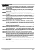
Figure 4-2 Shown With Left Cover Removed Fuel Filler Cap Spark Arrestor Spark Plug Wire Air Filter Oil Level Indicator Battery Pre−Start Checks Before the engine is started, several things must first be checked. 1. Place the generator set in an open, dry, well ventilated and reasonably level location. 2. If grounding is required for your application, check to make sure your unit is grounded properly (see Section 3). 3. Check the engine’s oil level, see Section 5. 4. Check the fuel level, see Section 5.
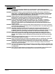
Figure 4-3 Connection Diagram GENERATOR CONTROL PANEL DC circuit breaker DC output terminal Diode rectifier Coil (1) Diode rectifier Org Brn/W Brn Brn Coil (2) R Grn/Y Grn/Y Key switch Coil (3) Blk R Blu Pur Gry Ignition coil Oil level sensor Org Blk Blu R Gry R Grn/Y R W W Stepping motor R AC receptacle (120V) Engine switch Earth (ground) terminal R Grn W W MONIT OR C/U Grn/Y Blu Y Blk Blu W INV&E/G C/U Brn W Blk Grn Org Org Blu R W Blu Main coil Grn/Y M− ST L.
Section 5 Troubleshooting and Maintenance WARNING: Before cleaning, inspecting, repairing, refueling or performing any maintenance to the generator set, always be sure the engine has stopped and that all rotating parts have also stopped. After stopping, certain components are still extremely hot so be careful not to get burned. WARNING: Before servicing the generator set, be sure to disconnect the spark plug wires to prevent accidental engine rotation or starting.
Clean/Adjust Spark Plug (Left side cover) 1. Remove the plug wire and spark plug. 2. .If the spark plug is contaminated, remove the carbon buildup with a plug cleaner or wire brush. 3. Adjust the electrode gap to 0.025 in. (0.6mm). NGKBR−6HS 0.024 − 0.028 in. 4. Install the spark plug and plug wire. or RL86C (0.6 − 0.7 mm) Clean Spark Arrester 1. 2. 3. 4. 5. Cleaning Remove the flange bolts from the muffler cover and remove the muffler cover.
Voltage Variations This generator set must be run at its proper speed to obtain the correct electrical power at its output. All engines have a tendency to slow down when a load is applied to it. The engine governor is designed to hold the operating speed as nearly constant as possible. When the electrical load is increased, the engine is more heavily loaded and engine speed drops slightly. This slight decrease in engine speed results in a slight decrease in generator voltage and frequency output.
Service Parts Engine Oil Service for your generator can be obtained from Baldor Generators. Please have the following information available prior to contacting the factory: The model number and serial number of the generator set. A complete and accurate description of the problem. Parts for your generator can be obtained from Baldor Generators. Please have the following information available prior to contacting the factory: The model number and serial number of the generator set.
Baldor District Offices UNITED STATES ARIZONA PHOENIX 4211 S 43RD PLACE PHOENIX, AZ 85040 PHONE: 602−470−0407 FAX: 602−470−0464 CALIFORNIA LOS ANGELES 6480 FLOTILLA COMMERCE, CA 90040 PHONE: 323−724−6771 FAX: 323−721−5859 HAYWARD 21056 FORBES STREET HAYWARD, CA 94545 PHONE: 510−785−9900 FAX: 510−785−9910 COLORADO DENVER 2520 W BARBERRY PLACE DENVER, CO 80204 PHONE: 303−623−0127 FAX: 303−595−3772 FAX: 586−978−9969 MICHIGAN Continued GAND RAPIDS 668 3 MILE ROAD NW GRAND RAPIDS, MI 49504 PHONE: 616−785−1784 F
WARNING: CALIFORNIA PROPOSITION 65 WARNING: Engine exhaust from this product contains chemicals known to the state of California to cause cancer, birth defects and other reproductive harm. WARNING: CALIFORNIA PROPOSITION 65 WARNING: Battery posts, terminals and related accessories are known to the state of California to cause cancer, birth defects and other reproductive harm. BALDOR ELECTRIC COMPANY P.O. Box 2400 Ft.