Series 29 Digital DC Control Installation & Operating Manual 9/03 MN792
Table of Contents Section 1 Quick Start . . . . . . . . . . . . . . . . . . . . . . . . . . . . . . . . . . . . . . . . . . . . . . . . . . . . . . . . . . . . . . . . . . . . . . . . . . . . . . . . . . . . . . 1-1 Minimum Connection Requirements . . . . . . . . . . . . . . . . . . . . . . . . . . . . . . . . . . . . . . . . . . . . . . . . . . . . . . . . . . . . . 1-1 Power and Motor Connections . . . . . . . . . . . . . . . . . . . . . . . . . . . . . . . . . . . . . . . . . . . . . . . . . . . . .
Blower Motor Starter . . . . . . . . . . . . . . . . . . . . . . . . . . . . . . . . . . . . . . . . . . . . . . . . . . . . . . . . . . . . . . . . . . . . . . 4-12 Thermal Protection . . . . . . . . . . . . . . . . . . . . . . . . . . . . . . . . . . . . . . . . . . . . . . . . . . . . . . . . . . . . . . . . . . . . . . . . 4-13 Encoder Installation . . . . . . . . . . . . . . . . . . . . . . . . . . . . . . . . . . . . . . . . . . . . . . . . . . . . . . . . . . . . . . . . . . . . . . .
Password . . . . . . . . . . . . . . . . . . . . . . . . . . . . . . . . . . . . . . . . . . . . . . . . . . . . . . . . . . . . . . . . . . . . . . . . . . . . . . . . 6-31 PID . . . . . . . . . . . . . . . . . . . . . . . . . . . . . . . . . . . . . . . . . . . . . . . . . . . . . . . . . . . . . . . . . . . . . . . . . . . . . . . . . . . . . 6-32 Raise/Lower . . . . . . . . . . . . . . . . . . . . . . . . . . . . . . . . . . . . . . . . . . . . . . . . . . . . . . . . . . . . . . . . . . . . . . . .
Manage Trips from the Keypad . . . . . . . . . . . . . . . . . . . . . . . . . . . . . . . . . . . . . . . . . . . . . . . . . . . . . . . . . . . . . . . . . . 8-4 Trip Messages . . . . . . . . . . . . . . . . . . . . . . . . . . . . . . . . . . . . . . . . . . . . . . . . . . . . . . . . . . . . . . . . . . . . . . . . . . . . 8-4 Symbolic Alarm Messages . . . . . . . . . . . . . . . . . . . . . . . . . . . . . . . . . . . . . . . . . . . . . . . . . . . . . . . . . . . . . . . . .
Section 1 Quick Start The basic steps for connection and setup are provided in this section. Detailed descriptions of each step and parameter settings are provided later in this manual. Be sure to comply with all applicable codes when installing this control. The Series 29 DC control is a one way control. That is, it is non–regen and cannot reverse direction. It operates in the forward direction only. All references to reverse operation or regen operation apply to the Series 30 DC Control only.
Reference and Jumpers for Remote Operation For remote operation, the speed reference and other connections are made at the terminal strip connector. Not all of these connections are shown in Figure 1-3.
and scroll the menu choices, and “M” goes to next level menu and “E” comes back up one menu level. Action Apply Power Description Keypad Display shows this opening message. Display FORWARD REF: Comments Local control display. 0.00% Press “PROG” key BALDOR DC DRIVE DC 4Q 15A Press “M” key DC 4Q 15A MENU LEVEL This message may be different for each control size. Press “M” key Access the menus. MENU LEVEL DIAGNOSTICS Press Scroll to “Configure Drive” menu.
Configure the drive parameters and block diagram connections. Action Description Press “M” key Display Comments DC 4Q 15A MENU LEVEL Press “M” key Access the menus. MENU LEVEL DIAGNOSTICS Press or Scroll to “Configure Drive” menu. MENU LEVEL SETUP PARAMETERS Press “E” when done.
Section 2 General Information Overview CE Compliance Enclosure Sizes Copyright Baldor 2002. All rights reserved. This manual is copyrighted and all rights are reserved. This document may not, in whole or in part, be copied or reproduced in any form without the prior written consent of Baldor. Baldor makes no representations or warranties with respect to the contents hereof and specifically disclaims any implied warranties of fitness for any particular purpose.
Product Notice Intended use: These drives are intended for use in stationary ground based applications in industrial power installations according to the standards EN60204 and VDE0160. They are designed for machine applications that require variable speed controlled three phase brushless AC motors. These drives are not intended for use in applications such as: – Home appliances – Mobile vehicles – Ships – Airplanes Unless otherwise specified, this drive is intended for installation in a suitable enclosure.
PRECAUTIONS: WARNING: Do not touch any circuit board, power device or electrical connection before you first ensure that power has been disconnected and there is no high voltage present from this equipment or other equipment to which it is connected. Electrical shock can cause serious or fatal injury. WARNING: Be sure that you are completely familiar with the safe operation of this equipment.
Caution: To prevent equipment damage, be certain that the input power has correctly sized protective devices installed as well as a power disconnect. Caution: Avoid locating the control immediately above or beside heat generating equipment, or directly below water or steam pipes. Caution: Avoid locating the control in the vicinity of corrosive substances or vapors, metal particles and dust.
Section 3 Getting Started Control Overview Control Loops In very simple terms, control of the DC motor is maintained by Control Loops. An inner Current Loop and an outer Speed Loop are used. These control loops are shown in the Block Diagram of Appendix C. From the keypad, you can select the control loops to be used by the Control to provide either: • Current Control • Speed Control (factory setting) Normally a current or speed feedback signal is applied to the appropriate loop to control the process.
Local and Remote Modes Determine what operating mode is best for your application. Four modes are possible, see Figure 3-2. Figure 3-2 Local and Remote Modes Local: Keypad Setting (Factory Setting) For local operation, use the keypad to change parameters or control operation. Remote: Terminal Strip Setting Process control and other applications may require the control to be used in remote mode with analog and digital input/output signals performing all control operations.
Source / Destination Tags The control is very flexible because of the programming capability. The software block diagram of the control is shown in Appendix C. Each logic block has inputs and outputs. These I/O points are called “Tags” because they have a tag number associated with it and shown in brackets “[tag]” . Some tags are read only values and some are read/write. Besides setting the value of each parameter, its source or destination connections can be programmed.
Programming Block A very important step to installing this control is to determine the configuration that will best implement your application. Each input and output of each block has an assigned tag number. Tags are connected in software much like jumper wires are used in hardware. The control is shipped with a factory set software connection. This may be changed at any time.
Table 3-1 Set Analog Input 1 for 4–20mA Continued Action Description Display Comments Press M Access Configure I/O menu. CONFIGURE ENABLE DISABLE Press Change Configure Enable to Enabled. CONFIGURE ENABLE ENABLED This is menu level 3. Before any parameter values can be changed, Configure Enable must be “Enabled” (it is normally disabled”). Note that the LED’s on Keypad are flashing until changed back to Disable. Press E Access Configure I/O menu.
3-6 Getting Started MN792
Section 4 Receiving and Installation Receiving & Inspection Location Baldor Controls are thoroughly tested at the factory and carefully packaged for shipment. When you receive your control, there are several things you should do immediately. 1. Observe the condition of the shipping container and report any damage immediately to the commercial carrier that delivered your control. 2. Remove the control from the shipping container and remove all packing materials.
Cover Removal To connect power and signal wires, the cover must be removed. This procedure describes how to access all terminal connections inside the control. 1. Loosen the two cover screws shown in Figure 4-8, then lift and remove the cover as shown. Figure 4-1 Top Cover Removal Lift and remove cover Cover Screws (2) 2. Locate the two 1/4 turn screws shown in Figure 4-2. Rotate each screw 1/4 turn CCW. This releases the control from the base.
Cover Removal Continued 3. The control and base are hinged and are opened as shown in Figure 4-3. Figure 4-3 Hinged Assembly Rubber Grommet Metal 360 Degree Coupling Coupling ÂÂ ÂÂ ÂÂ The knock–out panel is part of the base assembly to allow connections to be made. Use the correct size rubber grommet, conduit coupling or 360 degree coupling. Raise the control to expose the base Hinge Knock–out panel Control Base 360 Degree Coupling Mechanical Installation Mount the control to the mounting surface.
Optional Remote Keypad Installation (Enclosure rating of IP54 when correctly mounted). The keypad may be remotely mounted using optional Baldor keypad extension cable. Tools Required: • Center punch, file and screwdrivers (Phillips and straight) and crescent wrench. • #19 drill and drill motor . Figure 4-4 Remote Keypad Installation 1 2 5 4 3 Keypad ACBD01A01 CBLD030KP Bezel ACBD02A01 Mounting Instruction: 1. 2. 3. 4. 5. 6. 7. 8. Locate a flat mounting surface.
Electrical Installation All interconnection wires between the control, AC power source, motor, host control and any operator interface stations should be in metal conduits. Use listed closed loop connectors that are of appropriate size for wire gauge being used. Connectors are to be installed using crimp tool specified by the manufacturer of the connector. Only class 1 wiring should be used.
Electrical Installation Continued Isolation Transformer Sizing Use the information in Table 4-2 to select the KVA rating of the transformer based on the HP rating of the control. The secondary voltage will be the input voltage to the control and the impedance should be 2% or less. One exception to Table 4-2 is when the DC armature voltage is less than the AC input voltage. If this is the case, use the following formula: KVA + 0.
Electrical Installation Continued Figure 4-7 Size 1–5 Power Terminal Locations Size 1 and 2 Size 3 Power Connections Earth from AC Main Supply D3, D4 D1, D2 Motor Ground A+ Size 4 A– Field Connections D5, D6 D1 = FL1 D2 = FL2 D3 = F– D4 = F+ D5 = 3 D6 = 4 D7 = N D8 = L Size 5 Logic Supply, Contactor & Thermistor Connections D7, D8 Logic Supply, Contactor & Thermistor Connections Field Connections L1 L1 A+ L2 L3 L1 A- A+ L2 L3 L1 A+ A- L2 L3 L2 L3 THERM+ and THERM– are on separate
Electrical Installation Continued Power Connections Single phase operation of this control is not possible. Power connections are shown in Figure 4-8. (The location of these terminals is shown in Figure 4-9). Figure 4-8 3 Phase Power Connections L1 Note 1 L2 L3 Fuse Connection Earth Note 3 & 4 Notes: 1. See Protection Device description in this section. 2. Metal conduit or shielded cable should be used. Connect conduits so the use of a Reactor or RC Device does not interrupt EMI/RFI shielding. 3.
Electrical Installation Continued Motor Connections Motor connections are shown in Figure 4-10. (The location of these terminals is shown in Figure 4-9). Note: If your motor requires more than 85% of the line voltage as its DC input voltage, a step up transformer is required. This is added between the incoming line terminals and the L1 and L2 terminals of the field supply module. This connection is phase sensitive with main input L1 and L2.
Electrical Installation Continued External Field Terminal and Jumper Locations – Size 2 The position of the jumper selects the board to use either an internal or external motor field.
Electrical Installation Continued External Field Terminal and Jumper Locations – Size 4 and 5 Relocating the Red and Yellow phase wires (as shown in Figure 4-14) allows terminals FL1 and FL2 to be used as the external field AC supply connections. External fuse must not exceed 30A. Figure 4-14 External Field Connections Yellow ye llo Red r ed w F4 F4 F2 & F5 = Internal Field Supply. F3 & F6 = External Field Supply.
Electrical Installation Continued Figure 4-16 M Contactor Operation Sequence Turn-ON Run Time Turn-OFF M Contact 20 msec. Enable Motor Flux “Drive ON” Output Mech. Brake Release (If user installed) 50 msec. Brake Set Time Speed/Torque Command Blower Motor Starter Optional Size 1 and 2 controls only.
Electrical Installation Continued Thermal Protection Terminals TB3 TH1 and TH2 are available for connection to a normally closed thermostat or overload relay in all operating modes as shown in Figure 4-17. The thermostat or overload relay should be a dry contact type with no power available from the contact. If the motor thermostat or overload relay activates (opens), the control will automatically shut down and give an Thermistor fault.
Electrical Installation Continued Tachometer Installation The tachometer expansion board can be used to connect either an AC Tach or a DC Tach to the control (only one may be used). Shielded wire must be used for tachometer connection. Table 4-7 defines the tachometer connections to the tachometer expansion board. Figure 4-19 shows the electrical connections of the tachometer. Figure 4-20 shows the settings for this board. Note: DC Tachometers provide speed and direction feedback.
Control I/O Signal Connections All connections made to terminal blocks A, B and C must be isolated signal voltages. If in doubt a connection, contact Baldor. Only shielded, twisted pair cables should be use. Minimum wire size is 18AWG (0.75mm2). All cables should be installed using the appropriate coupling in the knock out panel, shown in Figure 4-3. Analog Inputs Five analog inputs are available, AnIn1 – AnIn5 (AnIn4 and AnIn5 are factory set for current limits).
Control I/O Signal Connections Continued Analog Outputs Connector Terminal A7, A8, A9 Signal Description Three analog outputs are available, AnOut1 – AnOut3. A1 is the 0V common reference point. Figure 4-22 Analog Outputs Analog Outputs 0V Digital Inputs Connector Terminal B8 B9 C2 C3 C4 C5 C6 C7 C8 A1 AnOut1 A7 Analog Output 1 (±10VDC) AnOut2 A8 Analog Output 2 (±10VDC) Arm I Fbk Control A9 Analog Output 3 (±10VDC) See Recommended Tightening Torques in Section 9.
Control I/O Signal Connections Continued Figure 4-23 Run/Stop Connections B8 Program Stop B9 Coast Stop C3 Start C4 Enable C5 Reverse C6 Jog/Slack C7 Jog/Slack Mode C8 Speed/Torque Select C9 +24VDC Control RE Emergency Stop Relay (Optional) (Shown in energized - Run position) See Recommended Tightening Torques in Section 9. A regenerative drive can be stopped using a Normal Stop, a Program Stop, or an Emergency Stop.
RS232 Connections The keypad connector shown in Figure 4-25 is used for RS232 communications. Workbench D is the 1 SERIAL LINKS block programming software for Windows PCs. It has a graphical user interface and drawing tools to allow you to create block programming diagrams quickly and easily. 2 SYSTEM PORT P3 Figure 4-25 System Port (P3) Keypad Connector 3 P3 SETUP MODE P3 BAUD RATE 1 2 View into the connector.
Section 5 Switch Setting and Start-Up Pre–Operation Checks When the installation is complete, several things should be verified before power is applied. 1. Be sure AC power is off at the main disconnect or circuit breakers. 2. Measure the main AC supply voltage (to the disconnect or breaker) and verify that it matches the nameplate rating of the control. 3. If the catalog number on the nameplate ends with “CO1”, an external 115VAC logic control supply is required (C02= 230VAC Logic).
Power up in Local Mode with Armature Feedback Continued 3. Action Apply Logic Power Set the parameter Configure Enable to “Enabled”. Description Keypad Display shows this opening message. Display FORWARD REF: 0.00% Press “PROG” key BALDOR DC DRIVE DC 4Q 35A Press “M” key DC 4Q 35A MENU LEVEL Press “M” key Access the menus. MENU LEVEL DIAGNOSTICS Press Scroll to “Configure Drive” menu. MENU LEVEL CONFIGURE DRIVE Press “M” key Access Configure Drive menu.
Power up in Local Mode with Armature Feedback Continued 6. Action Set the Field Current. Note the nominal field current from the motor rating plate and set this value in the Field Current parameter. Description Press Scroll to the Field Current parameter.
Power up in Local Mode with Armature Feedback Continued The control is now ready to run from the keypad using armature feedback. 1. The logic power is still applied, the keypad display is normal, the motor is connected but the load is removed. 2. Apply 3 phase power. 3. Verify that the keypad and LED displays are still normal, with no error messages. 4. Set the Speed Setpoint parameter to zero. 5. Verify that the Main CURR. Limit is set to 0.00%.
Power up in Remote Mode with Feedback This procedure assumes that the terminal strip (connectors A, B C) are wired according to the instructions provided in Section 4 and the feedback device is properly installed. (The start up mode is defined by Parameter [517] =False for remote operation which is the same as “SETUP PARAMETERS::OP STATION::START UP VALUES::LOCAL = FALSE”.) When pre–operation checks are complete, logic power can be applied to setup the software parameters.
Power up in Remote Mode with Feedback Continued 5. Action Set the Armature Current. Note the maximum armature current from the motor name plate and set this value in the Armature Current parameter. Description Display Press Scroll to the Armature Current parameter. CONFIGURE DRIVE CONFIGURE ENABLE Press “M” key Access the Armature Current parameter CONFIGURE DRIVE ARMATURE CURRENT Press “PROG” key ARMATURE CURRENT 11.5 AMPS 6. Action Press Scroll to the Field Current parameter.
Power up in Remote Mode with Feedback Continued 9. 10. Action Set the Configure Dive::Configure Enable parameter to disable (see step 3). Save the settings. Description Start at Menu Level 1 Press Display Comments MENU LEVEL DIAGNOSTICS Scroll to “PARAMETER SAVE” menu. Press “M” key MENU LEVEL PARAMETER SAVE PARAMETER SAVE UP TO ACTION Press Press to save parameters. Press “E” key Exit one level PARAMETER SAVE REQUESTED Parameters are saved. Except the “Local Setpoint”.
Power up in Remote Mode with Feedback Continued 8. 9. Action Verify that C9 is +24VDC (reference to B1), and that B3 is –10VDC (reference to B1). Select the Speed Feedback type. Description Display Press Scroll to “Configure Drive” menu. Press “M” key Access Configure Drive menu. CONFIGURE DRIVE CONFIGURE ENABLE Press “M” key Access the Configure Enable parameter. CONFIGURE ENABLE DISABLED Press Enable Configure Enable.
Power up in Remote Mode with Feedback Continued 14. 15. Action Set the Configure Dive::Configure Enable parameter to disable (see step 9). Save the settings. Description Start at Menu Level 1 Press Display Comments MENU LEVEL DIAGNOSTICS Scroll to “PARAMETER SAVE” menu. Press “M” key MENU LEVEL PARAMETER SAVE PARAMETER SAVE UP TO ACTION Press Press to save parameters. Press “E” key Exit one level 16. PARAMETER SAVE REQUESTED Parameters are saved. Except the “Local Setpoint”.
e. Is the FLD CTRL Mode parameter set to Voltage Control or Current Control? If set to Voltage Control, check the value of the FLD. Volts Ratio parameter. Set this to 65% to obtain 300V fields from 460V lines. If set to Current Control, check the field current calibration set–up, refer to “Calibration”. 22. Verify that the OK and STOP LEDs are On, also either the FWD or REV LED. Note that all external interlocks that affect the Enable input C4 will affect the operation of the drive.
Power up in Remote Mode with Feedback Continued Note: Reverse Operation is possible with the Series 30 REGEN Drives only. 31. With the MAIN CURR.LIMIT parameter set to 20% or the level required to achieve rotation, set the value of the Speed Setpoint to 10%, 1.0V at setpoint input. The motor will accelerate to this speed setting. 32. Adjust the Zero Speed parameter (Ensure Standstill is Disabled). a.
Power up in Remote Mode with Feedback Continued Autotune 8. Reset the MAIN CURR. LIMIT to 100% to correspond to 100% full load current (FLC). Note: The controller cannot achieve 200% current unless the CUR LIMIT/SCALER parameter is increased to 200% (from its factory setting of 100%). Until this is done, the External Current Clamp will limit the current to 100%. a.
Speed Loop Adjustment You will need to adjust the Speed Loop for your application although in most cases the factory 1. 2. settings are acceptable. The optimum Speed Loop performance is achieved by adjusting the PROP. Gain and INT. Time CONST. parameters. Produce a small step–change to the speed setpoint and observe the response on the tachometer feedback or analog output set to speed feedback. Adjust PROP. Gain and INT. Time CONST.
Starting and Stopping Methods Continued Normal Stop Action – Remove 24V from Terminal C3 to stop. The motor speed is brought to zero in a time defined by the Stop Time parameter. Normal Stop Speed Setpoint (100%) Control Signals Start/Run (C3) t 0% Speed Demand Speed Demand 100% = Speed Setpoint t 0% Stop Time (10 Seconds) Speed Feedback Actual Speed Actual stopping rate depends on load inertia, motor hp, and overload capability of the drive.
Starting and Stopping Methods Continued Program Stop (terminal B8) Action – Remove 24V from Terminal B8 to stop. The motor speed is brought to zero by conditions defined in PROG. Stop Time (ramp rate) and PROG. Stop I Limit parameters. Program Stop Timing Speed Setpoint (100%) Control Signals Program Stop 0% Speed Demand LED Off LED On (Program Stop False) (Program Stop is a latched funtion) Speed Demand 100% = Speed Setpoint t 0% Prog Stop Time (0.
Starting and Stopping Methods Continued Coast to Stop (terminal B9) Action – Remove 24V from Terminal B8 to stop. The motor speed is brought to zero by conditions defined in the PROG. Stop Time (ramp rate) and PROG. Stop I Limit parameters. The control output is automatically quenched and the contactor is opened. The motor coasts to a stop. The motor coast stop rate is dictated by the motor and load inertia – the drive does not control the motion.
Upload/Download Procedure (UDP) 1 SERIAL LINKS 2 SYSTEM PORT P3 DUMP MMI (TX) UDP XFER (RX) UDP XFER (TX) MN792 Upload This procedure will transfer the parameters from a file at the host computer to the non–volatile memory of the Control. This information is written directly to EEPROM, so all the drive’s settings are overwritten. The procedure is as follows: 1. Verify the Control is properly connected to the PC. 2. Use a standard communications software package installed at the PC.
DUMP ProcedureThis procedure will transfer the control’s settings in a text format that is clear and easy to read. 1. 2. 3. 4. 5. 6. 7. Verify the Control is properly connected to the PC. Use a standard communications software package installed at the PC. Set the COM port for 9600, 8, 1, None. Prepare the PC communications software to receive a standard ASCII text file (Capture mode); use the file extension .UDP to differentiate it from .MMI format files. Perform a PARAMETER SAVE of the Control’s settings.
Section 6 Programming Overview The shipping configuration allows the user to start up and run a DC motor in simple speed control. The flexibility is having the ability to change configuration and to tune the control for optimum performance. The parameters most frequently adjusted for tuning and performance are in the Setup Parameters menu. They are categorized by submenus within the overall software block diagram. This chapter describes each of these parameters.
Parameter Types Each drive parameter is associated with a unique address, or “tag.” When “connecting” any parameter to drive inputs, outputs, or links, this tag is designated as the source or destination address. These drive parameters are listed by tag number, parameter name and menu group name in the appendix of this manual. There are only two types of parameters: logic or value. Logic Logic parameters are boolean – or either On (1) or Off (0).
Figure 6-1 1 Diagnostics Setup Parameters 2 3 Ramps Setup AUX I/O Local Ramp OP Station Startup Values 4 Menu Levels Jog / Slack Raise / Lower Password Alarm Status Special Blocks PID Field Control FLD Voltage VARS Current Profile FLS Current VARS FLD Weak VARS Speed Loop Advanced Adaption Standstill Setpoints Zero SPD Quench Stop Rates Calibration Inhibit Alarms Menus Current Loop Setpoint Sum 1 Serial Links 5703 Support TEC Option System Port (P3) P3 Setup Bisynch Supp
Parameter Descriptions Analog Inputs Five analog input blocks are used to scale and clamp the inputs for terminals A2 through A6. Analog input 1 is the 0–20mA or 4–20mA input. Analog input 2 is the main speed loop input (without Accel/Decel ramps). Analog input 3 is Speed setpoint no. 3. Analog input 4 is the negative current clamp; this is only active if bipolar clamps are enabled; ANIN 5 – Main current limit (or positive current clamp if bipolar clamps are enabled.
Analog Inputs Continued Input Description Analog input 1 Used as a unipolar 0–20mA ramped speed command channel. Output [246] is connected to Setpoint Sum 1, Terminal (A2) Input 1. To use 4–20mA requires setting the Min value to 25%, the Max Value to 125% and the Setpoint Sum1, Input 2 to (–)25%. These settings provide the proper scaling and offset to set 4mA to zero command. An input value less than 4mA results in a Min Value of 25% being summed with the (–)25% at the Setpoint Sum 1 summing junction.
Analog Outputs Three Analog Outputs are available, A7, A8 and A9. A7 and A8 can be configured and the source of an analog output signal can be read from any parameter. It is important to remember that other parameters do not “send” signals to the output terminal. An output terminal “retrieves” the signal from the parameter described by its Source Tag parameter. A9 is the armature current output and cannot be changed.
Calibration Board Power Board Analog Outputs Continued Example 1 – Read the field current feedback using Analog Output 1. The tag number for the field current feedback parameter is 300. 1. Set CONFIGURE I/O::CONFIGURE ENABLE to Enable. 2. Set ANALOG OUTPUTS::ANOUT 1 (A7):: SOURCE TAG to 300. 3. Set ANALOG OUTPUTS::ANOUT 1 (A7):: % TO GET 10 VDC to 100% (factory setting). 4. Set SETUP PARAMETERS::CALIBRATION::ARMATURE I (A9) to Bipolar (factory setting). 5. Reset CONFIGURE I/O::CONFIGURE ENABLE to Disable.
AUX I/O The auxiliary I/O parameters allow an external computer (or PLC) to control the Start, Jog and Enable terminals. Start, Enable and Jog digital input terminals C3, C4, C6 and C7 respectively connect directly to the AUX I/O block. Output signals are then sent to the drive start and drive enable logic and the Jog/Slack function block. 1 SETUP PARAMETERS 2 AUX I/O AUX Start AUX Jog AUX Enable AUX Digout 1 AUX Digout 2 AUX Digout 3 ANOUT 1 ANOUT 2 Jog/Slack REM. SEQ.
AUX I/O Continued Functional Description The external device sends its signal directly to the required tag (PNO). In the case of auxiliary digital inputs AUX Start, AUX Jog and AUX Enable, the overall input will be the result of the “AND” gating of the normal terminal signal with the auxiliary signal from an external computer or PLC. The remaining auxiliary outputs allow external computers to directly control the output terminals. These connections are set in SYSTEM::CONFIGURE I/O.
AUX I/O Continued Example Bit Patterns Sequence Status 0001 1011 0000 1011 0000 0100 0100 1011 0000 0100 0100 0111 0000 1100 0100 0111 Comment Running Tripped, Run High Tripped, Run Low, Enable Low Trip Acknowledged, Healthy o/p TRUE Alarm stays high until drive is restarted. Example Serial commands using EI–ASCII – REM.
Block Diagram The Block Diagram parameters make the connections of input and output tags for the blocks identified on the block diagrams of Appendix C. These connections are only executed when the destinations are connected to a non–zero tag. If a function is not required, set its destination tag to zero. A tag=0 causes the processor to ignore the function and reduces processor loading. Note: Only the connections are described here.
Calibration This block contains parameters specific to the motor. Note: Control operation is suspended and all Keypad LEDs will flash while the Configure Enable = Enabled. 1 SETUP PARAMETERS Calibration – Functional Diagram Tag Parameter Factory Setting 2 CALIBRATION These parameters can also be set in the Level 1 Configure Drive" menu.
Calibration Continued Parameter Descriptions Continued Encoder RPM Max motor speed when using encoder feedback. Encoder Lines Sets the lines per revolution value of the encoder being used. Analog TACH CAL Trim adjustment of the motor speed to give exactly 100% at the required actual speed value (e.g. 1500 RPM etc). Note: Primary tachometer calibration is achieved by adjusting SW1 – 3 on the tachometer calibration board. Zero SPD.
Configure Drive This menu contains many of the parameters required for configuring the drive. The Configure Drive menu is only available at the keypad. Note: Control operation is suspended and all Keypad LEDs will flash while the Configure Enable = Enabled.
Current Loop Allows parameters to be customized for the conventional current loop (torque loop) of the control.
Current Loop Continued Parameter Descriptions At Current Limit (Read in Diagnostics Parameters) True indicates that current demand equals or exceeds maximum current limit. IA Demand (Read in Diagnostics Parameters) (IaDmd Unfiltered) IA Feedback (Read in Diagnostics Parameters) (IaFbk Unfiltered) Current FBK.AMPS (Read in Diagnostics Parameters) Scaled and filtered armature current in Amps. IF Feedback (Read in Diagnostics Parameters) (Field I FBK.AMPS) Autotune This is the autotune function trigger input.
Current Profile When speed control is obtained by field weakening, the ability of the motor to commutate armature current is reduced at low field currents. Also some motors exhibit commutation limitations at higher speeds even with rated field current. 1 SETUP PARAMETERS Current Profile 100.0% 100.0% 200.0% 200.
Diagnostics This function block is used to monitor the status of the drive, internal variables, and its inputs and outputs.
Diagnostics Continued Parameter Descriptions Inverse Time Output (shown in Current Loop block) Inverse time clamp output level. At Current Limit (shown in Current Loop block) Current demand is being restrained by the overall current limit. At Zero Speed (shown in Standstill block) At zero speed feedback. At Zero Setpoint (shown in Standstill block) At zero speed demand. At Standstill (shown in Standstill block) At zero speed and at zero setpoint.
Diagnostics Continued Parameter Descriptions Digital Input C4 Enable terminal. Digital Input C5 Reverse terminal. DIGIN 1 (C6) Jog/Slack terminal. DIGIN 2 (C7) Jog/Slack Mode terminal. DIGIN 3 (C8) Speed or Torque mode select terminal. DIGOUT 1 (B5) (shown in Digital Outputs block) At zero speed. DIGOUT 2 (B6) (shown in Digital Outputs block) Drive healthy. Health is also displayed on the front panel LED.
Digital Inputs Allows control of the digital operating parameters of the software. The digital input can be configured to point to a destination location and to set that destination true or false depending upon programmable values. 1 SYSTEM 1 SYSTEM 2 CONFIGURE I/O Digital Input 1 – DIGIN 1 (C6) Tag 2 CONFIGURE I/O Digital Input 1 3 DIGITAL INPUTS 3 DIGITAL INPUTS 4 DIGIN 1 (C6) 4 DIGITAL INPUT C4 4 DIGIN 2 (C7) 4 DIGITAL INPUT C5 Setting 90 0.00% 0.
Digital Inputs Continued Functional Description The destination for a digital input can be any valid Tag number. This means that a digital input can be used to select one of two values for a given parameter. It is also possible to treat the values for true and false as destination tags from other functions or inputs. 0.00% = a Logic 0 and any other value = a Logic 1. This refers to the values set in both value for true and value for false parameters.
Digital Inputs Continued Digital input 1 now sends a 0 when the input signal is true and 1 when it is false. Digital Input 1 – DIGIN 1 (C6) Tag Digital Input 1 [102] [104] [103] Parameter Destination Tag Value for False Value for True Setting 90 0.01% 0.
Digital Inputs Continued Example 4 – Use Digital Input 1 to switch signal sources 1. Set CONFIGURE I/O::CONFIGURE ENABLE to ENABLE. 2. Set DIGIN 1 (C6)::DESTINATION TAG to 364 (Link 1 source tag parameter). 3. Set DIGIN 1 (C6)::VALUE FOR TRUE to 1.29% (tag number for AUX I/O::ANOUT 2=129). 4. Set DIGIN 1 (C6)::VALUE FOR FALSE to 1.28% (tag number for AUX I/O::ANOUT 1=128). 5. Set LINK 1::DESTINATION TAG to 309 (SETPOINT SUM::INPUT 0 parameter). 6. Set AUX I/O::ANOUT 1 to 10%. 7. Set AUX I/O::ANOUT 2 to 20%.
Digital Outputs Digital outputs can read all parameters (the same as the analog outputs). When used with a VALUE parameter, MODULUS removes the sign from the value (so –100 becomes 100). The THRESHOLD (>) parameter determines when the output is HIGH or LOW. The input signal must exceed the Threshold value for the output to go HIGH. INVERTED, when TRUE, inverts the result of the output from the threshold test.
Field Control This function block contains all the parameters for the field operating mode. It is viewed at the keypad in three submenus. In the Field Control menu, you select the field operating mode: open loop voltage control or closed loop current control. In certain DC motor applications, high speeds can only be achieved by reducing the field current (torque). This is the constant horsepower region or field weakening region, and the speed at which it begins is known as the Base Speed.
Field Control Continued Parameter Descriptions MAX VOLTS The voltage level at which field weakening begins. It is also known as “Spillover Bias”. The factory setting value is 100% of the nominal value as set by the armature voltage calibration value. For start–up this value can be set to a lower desirable level. It is advisable to return it to 100% for normal operation.
Alarms 1 SETUP PARAMETERS This function block provides a view into the present and past trip conditions, and allows some trips to be disabled. It is viewed at the keypad in three menus. 1 ALARM STATUS 2 INHIBIT ALARMS) Field Fail 5703 RCV Error Stall Trip Trip Reset Speed FBK Alarm Encoder Alarm REM Trip Inhibit Last Alarm Health Word Health Store Stall Trip Remote Trip Field current less than 6%. (Field fail threshold is 6% in Current control, 12% in Voltage control.
Jog/Slack These parameters control the Jog function of the control. (Also see “Ramps” description). 1 SETUP PARAMETERS DIG IN 1 [C6] 2 Jog/Slack Jog Speed 1 Jog Speed 2 Take Up 1 Take Up 2 Crawl Speed Mode Ramp Rate [C7] [102] [105] Jog / Slack Tag Parameter [496] Jog/Slack Factory Setting [228] Mode False [212] Operating Mode Stop [253] [254] [218] [219] [225] [355] Take Up 1 Take Up 2 Jog Speed 1 Jog Speed 2 Crawl Speed Ramp Rate +5.00% -5.00% +5.00% -5.00% 10.00% 1.
Menus Allows selection of either the full menu structure, or a reduced menu structure. It also selects the language for the keypad display. 1 MENUS Menus 1 SETUP PARAMETERS Full Menus Language 4 SPEED LOOP Speed FBK Filter Enabled 0.000 English [37] Full Menus [547] Speed FDBK Filter [304] Language Parameter Descriptions FULL MENUS When enabled, the full menu structure is displayed at the keypad. LANGUAGE Selects the display language. Other languages are available, please contact Baldor.
OP Station (Keypad) Local operation parameters are set using three menus. 1 SETUP PARAMETERS 1 SETUP PARAMETERS 2 OP-STATION 2 OP-STATION 3 SETUP 3 START UP VALUES Set Point JOG Setpoint Local Key Enable 1 SETUP PARAMETERS Setpoint JOG Setpoint Forward Program Local Ramp ACCEL Time Ramp DECEL Time Local Ramp Down Key Note: Local Setpoint (only active when the drive is in Local mode) Accel Time Decel Time % S-Ramp Parameter Descriptions Local Key Enable Enables the “L/R” on the keypad.
PID 1 SETUP PARAMETERS 2 SPECIAL BLOCKS 3 PID PROP Gain INT Time CONST Derivative TC Positive Limit Negative Limit O/P Scaler (Trim) Input 1 Input 2 Ratio 1 Ratio 2 Divider 1 Divider 2 Enable INT Defeat Filter TC Mode MIN Profile Gain Profiled Gain This is a general purpose PID block which can be used for many closed loop control applications. PID feedback can be loadcell tension, dancer position or any other transducer feedback such as pressure, flow etc.
PID Continued Parameter Descriptions FILTER T.C. Range: 0.000 to 10.000 To attenuate high–frequency noise, a first order filter is added in conjunction with the differentiator. Seconds The ratio k of the Derivative Time Constant (Td) over the Filter Time Constant (Tf) (typically 4 or 5) determines the high–frequency lift of the transfer function. For Tf = 0 this filter is disabled. MODE Range: 0 to 4 This determines the law which the profiler follows versus diameter.
Raise/Lower Provides a motor operated potentiometer (MOP) feature. Raise input [261], when true, increases the output at the rate determined by increase rate [256]. Lower input [262] decreases the output as determined by decrease rate [257]. MIN value and MAX value limits the total change by the amounts set. The output is not preserved during power–down.
Ramps This function block provides the facility to control the rate at which the control will respond to a changing setpoint. 1 SETUP PARAMETERS DIG IN R 2 RAMPS [C5] Ramp ACCEL Time Ramp DECEL Time Constant ACCEL Ramp Hold % S-Ramp Ramping Thresh Auto Reset External Reset Reset Value MIN Speed DIG IN 1 [102] DIG IN 2 [C7] [105] [620] [5] [126] [286] Factory Setting Ramp Invert Ramp Input Min Speed Ramping Threshold False 0.00% 0.00% 0.
Ramps Continued Parameter Descriptions Reset Value This value is loaded into the output when Ramp Reset is true, or at power–up. To catch a spinning load smoothly (‘bumpless transfer’), connect Speed Feedback [62] (source) to Reset Value [422] (destination). MIN. Speed The minimum speed clamp is fully bi–directional and operates with a 0.5% hysteresis. This clamp operates on the input to the ramp and it can therefore be overrridden by the Reset Value (as far as the ramp output is concerned).
Ramps Continued Minimum Speed 100% X% Drive Enabled Ramp Input Ramp Input 0% t0 t t0 t 100% X% This figure shows the effect of setting MIN. Speed above 0.00%. When the drive is enabled, the ramp output cannot decrease below the MIN. Speed value. Note the ramp rates are used when changing the output from minimum speed to zero speed. Notice also that in this example the ramp output only increases to X% since the ramp input signal is limited to X%.
Setpoint Sum 1 Setpoint Sum 1 allows the summing and scaling of three analog inputs to produce SPT. Sum Output [294]. Note: This block is ignored by the drive unless [294] is connected to a nonzero destination tag. Input 0 and Input 1 have individual ratio and divider scalers, and signs. Input 1 has an additional deadband function set by Deadband Width. When the input is within the deadband, the output clamps to zero to ignore any noise.
Speed Loop Speed loop selects the speed feedback source and tunes the speed loop PI to produce a current demand. The parameters are set in several menus, some parameters can be set in multiple menus. Speed FBK Select determines the source of the speed feedback signal. The default, Arm Volts FBK, uses internal circuitry to derive speed feedback. The other selections require external devices to provide the feedback signal. Speed Demand is summed algebraically with Speed Feedback to yield Speed Error.
Speed Loop Continued Parameter Descriptions Speed Loop Output SPD Loop Output (Read in Diagnostics Parameters) Output from Speed Loop PI. Speed Feedback (Read in Diagnostics Parameters) The speed feedback value from the source chosen by SPEED FBK SEL. Speed Setpoint (Read in Diagnostics Parameters) Speed loop total setpoint including the ramp output before the ramp–to–zero function. Speed Error (Read in Diagnostics Parameters) Speed loop error. Speed PROP. Gain (Can be set in Speed Loop or Configure Drive.
Speed Loop Continued Advanced This function block is shown in Speed Loop Adaption Adjusts speed loop gain scheduling. Zero SPD Quench Similar to Standstill logic (i.e. keeps the contactor in but motor current drops to zero) except the speed loop stays enabled and will cause the current loop to unquench very quickly.
Standstill Standstill logic is used to inhibit rotation during Zero Speed demand. If the drive is below the zero speed threshold [12] and Standstill Logic [11] is enabled, the speed and current loops are quenched to prevent shaft oscillation around zero speed. Standstill Logic is useful in maintaining absolute zero speed but can cause problems in web handling applications using tension feedback. At zero speed, the SCR’s turn off allowing web tension to pull the driven roll in reverse.
Stop Rates Sets the stop method parameters for the control. A normal stop occurs when the Run signal is removed from terminal C3. It ramps the speed demand to zero at a rate set by Stop Time. Series 29 Non–regenerative drives will stop no faster than the coast stop rate. Series 30 Regenerative drives use Stop Time to set the duration of the stop. After the stop, the contactor de–energizes and the drive disables. The Stop Limit timer starts when C3 goes to zero volts.
Stop Rates Continued Functional Description Stop Hierarchy Coast Stop – Terminal B9 • Disables the drive and opens the contactor using the pilot output Enable – Terminal C4 • Suspends and resets the control loops Program Stop – Terminal B8 • Independent ramp time • Stop Timer • Independent current limit may be greater than normal current limit • Independent zero speed Normal Run/Stop – Terminal C3 • Independent ramp time • Contactor Delay Note: The Control’s reaction to commands is defined by a state machin
Stop Rates Continued Time Out During a Normal Stop When a normal stop takes longer than the Stop Limit time, the control disables and the contactor is de–energized. 100 Start / Run (C3) Speed Setpoint % 0 100 Speed Demand % 0 Stop Time 10.0 Seconds 100 Speed Feedback % 0 2 Stop Zero Speed 2.00% Contactor drops out if Speed Feedback > Stop Zero Speed when Stop Limit times out.
Stop Rates Continued Normal Program Stop Sequence Program Stop is a latched operation. When a Program Stop command is received (B8 goes to zero volts), the stop continues even if 24 volts is restored at terminal B8. 100 Program Stop Speed Setpoint % LED On (Program Stop = False) LED Off 0 100 Speed Demand % 0 PROG Stop Time 0.10 Seconds 100 Speed Feedback % 0 2 Stop Zero Speed 2.00% Current Limit is set by PROG Stop I Limit [91].
Stop Rates Continued Time Out During a Normal Program Stop The time out operation is the same for both a normal stop and a program stop. 100 Program Stop Speed Setpoint % LED On (Program Stop = False) LED Off 0 100 Speed Demand % 0 PROG Stop Time 0.10 Seconds 100 Speed Feedback % 0 2 Stop Zero Speed 2.00% Contactor drops out if Speed Feedback > Stop Zero Speed when PROG Stop Limit times out.
System Port P3 The System Port (P3) is a non–isolated RS232 serial communications port. The port is used off–line (while the drive is stopped) for transferring and saving drive configuration files using a personal computer (PC) running a serial communications program, or online (while running) with the Peer–to–Peer Communications control. You can also use the P3 port to transfer configuration files with a PC running Workbench D software. Three menus are used to configure the serial port.
System Port P3 Continued Communication Port Setup For UDP data and text file transfers, set the host computer communication port settings as follows: 9600 Baud 8 bits 1 Stop bit XON/XOFF handshaking NO parity UDP transfer procedure Note: Set the P3 Baud Rate to match the PC’s COM port baud rate (9600 is recommended). P3 Port Connector 1234 P3 Pin No. Signal Name 1 2 3 4 0VDC 24VDC Tx Rx DB9 Pin No. Female Male 5 5 No Connection No Connection 2 3 3 2 DB25 Pin No.
System Port P3 Continued UDP Download (UDP XFER From P3) A UDP download transfers the actual parameter and configuration settings from the control to a host computer. This file fully transfers all settings stored in EEPROM in a binary format and can be used as a back up file if the current drive settings are lost or if the drive is replaced. Note: A UDP download transfers settings stored in EEPROM since the last Parameter Save was performed.
5703 Support The 5703 peer–to–peer communication option is not available. 1 SERIAL LINKS 1 SYSTEM 2 SYSTEM PORT P3 2 CONFIGURE I/O 3 P3 SETUP 3 CONFIGURE 5703 4 5703 SUPPORT Source Tag Destination Tag 5703 89 0.0000 Positive Destination Tag [135] Scaled Input [189] Raw Input [187] [134] Source Tag [131] SETPT Ratio [132] SETPT Sign 0.00% SETPT Ratio SETPT Sign Raw Input Scaled Input Parameter Descriptions Scaled Input Scaled input. Raw Input Raw input.
TEC Option The Technology Option function block sets the inputs and outputs of the communications board options if installed. If a communications board is installed, refer to its manual for additional information.
Section 7 Keypad Operation Keypad The keypad allows full use of the Control’s features. The keypad provides “Local” motor control, status monitoring, and complete access for application programming. The display, LEDs and keys are shown in Figure 7-1. The Keypad Display displays the status information during local or remote operation. Figure 7-1 Keypad Indicator Lights (Also see Tables 7-1, 7-2, 7-3) OK Indicates general health status.
Keypad LED Status Seven LEDs indicate the status of the Control. Each LED (Figure 7-1) can operate in three different ways: Off , Blink , and On . Table 7-1 Control Status OK Run Stop Control Status Re–Configuration Tripped Stopped Stopping Running with Zero Reference Running Autotuning FWD REV Forward/Reverse Status Commanded direction and actual direction are Forward. Commanded direction and actual direction are Reverse (Series 30 only).
Local Menu L R key (Figure 7-2) Pressing the L/R key from anywhere in the Menu System activates the Local menu. The Local menu provides setpoint information for local operation. Pressing and holding the M key in the Local menu will display additional Feedback information. A display of forward or reverse feedback or reference whichever was previously selected by the FWD/REV key. Pressing the “M” key changes between feedback and reference.
Menu System The menu system is divided into nine major selections, shown in Table 7-4. Each selection has a structure of menus (Figure 7-3). At the keypad, press “M” to access the menus. Then press the or key to scroll through the menus. Table 7-4 The Keypad Display of the Main Menus Action Description Apply Power Display FORWARD REF: Press “PROG” key Comments 0.00% BALDOR DC DRIVE DC 4Q 15A Press “M” key 2 times Access the menus. DC 4Q 15A MENU LEVEL Press Scroll to next menu.
Figure 7-3 The Menu Map 1 Diagnostics Setup Parameters 2 3 Ramps Setup AUX I/O Local Ramp OP Station Startup Values 4 Menu Levels Jog / Slack Raise / Lower Password Alarm Status Special Blocks PID Field Control FLD Voltage VARS Current Profile FLS Current VARS FLD Weak VARS Speed Loop Advanced Adaption Standstill Setpoints Zero SPD Quench Stop Rates Calibration Inhibit Alarms Menus Current Loop Setpoint Sum 1 Serial Links 5703 Support TEC Option System Port (P3) P3 Setup
Menu Shortcuts and Special Key Combinations Quick Tag Information In any menu system, when a parameter is displayed hold down the “M” key for approximately 1/2 second to display the tag number for that parameter. In section 3, the example was given as shown in Figure 7-4. Each parameter has a tag number associated with it. For example, the Output of Analog Input 1 has a tag number of [246]. The value of tag [246] is 100. Input 1 parameter of Setpoint Sum 1 has a tag number of [100].
3 button reset (Changing the Power Base). This is only necessary if you are installing a new control board on an existing power base. Power–up the drive holding three keys as described in Figure 7-6. It is important that the control be configured for the correct power rating damage may occur to the drive when it attempts to run the motor. Continue to select the correct product code rating. Perform a parameter save now (refer to Save Settings).
Operation Examples Select a Menu View Level Two view levels are available: Full view or Reduced view. These were illustrated in Figure 7-3. 1 MENUS FULL MENUS LANGUAGE Full view shows all menu choices. Reduced view only shows a portion of the menu items. Action Apply Power Description Keypad Display shows this opening message. Display FORWARD REF: Press “PROG then press “M” 2 times Access the menus. MENU LEVEL DIAGNOSTICS Press Scroll to “MENUS” menu.
Password Protection A password prevents unauthorized parameter modification by making all parameters “read–only”. If you attempt to modify a password protected parameter, it will cause “PASSWORD ??” to be displayed. The 1 PASSWORD password protection is activated or deactivated using the ENTER PASSWORD and CHANGE PASSWORD ENTER PASSWORD parameters. CHANGE PASSWORD Activated: ENTER PASSWORD and CHANGE PASSWORD values are different. Deactivated:ENTER PASSWORD and CHANGE PASSWORD values are same.
Deactivate a Password 1 PASSWORD ENTER PASSWORD CHANGE PASSWORD When password protection is activated, you can no longer edit the CHANGE PASSWORD parameter until you deactivate the password protection (the value is displayed as “****”). First, enter the current password (e.g. 0x0002) in the ENTER PASSWORD parameter. Action Apply Power Description Keypad Display shows this opening message. Display FORWARD REF: 0.00% Comments This message is different for each control.
Save Settings When parameter values have been changed they are not permanent until they are saved. If you turn power off 1 SYSTEM 2 CONFIGURE I/O CONFIGURE ENABLE then turn power on, the previous settings (stored in memory) will be used. To make your new parameter settings the power up settings, they must be saved to non–volatile memory. These new values are always used until this procedure is used to write new values to non–volatile memory.
7-12 Keypad Operation MN792
Section 8 Troubleshooting Overview When a trip occurs, the Control’s power stage is immediately disabled (tripped) causing the motor and load to coast to a stop. The trip remains until action is taken to reset the fault, even if the original cause of the trip is no longer present. If a trip condition is detected the following occurs: 1. The “OK” LED goes off indicating a trip condition has occurred. (Investigate, find and remove the cause of the trip.) 2. Terminal B6 (Healthy) goes low (0V).
Alarm Messages When a trip occurs an alarm message is displayed at the keypad and information about the trip is stored in the Alarm Status menu. The alarm message and the Last Alarm parameter are displayed. The Health Store and Health Word parameters display information as hexadecimal values (0 – 9 and A, B, C, D, F shown in Table 8-1), or the sum of the hexadecimal values when more than one alarm is active. Therefore, the value can represent one or more alarms.
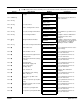
Table 8-3 14 14 14 14 14 14 14 14 Trip Autotune error Autotune aborted External trip Remote trip CONFIG Enabled No OP–Station PCB Version Product code F F F F F F F F LAST ALARM only 0 0 0 0 0 0 0 0 2 0 4 0 F 0 F 0 1 2 5 6 0 0 5 6 When more than one trip is to be represented at the same time then the trip codes are simply added together to form the value displayed. Within each digit, values between 10 and 15 are displayed as letters A to F shown in Table 8-1.
Manage Trips from the Keypad Trip Messages Most of the alarms have a delay timer so that the control only trips if the condition persists for the whole of the delay period. If the control trips, the display immediately shows a message indicating the reason for the trip. These messages are shown in Table 8-4. Table 8-4 Trip Message and Description Overspeed Motor overspeed – the speed feedback signal has exceeded 125% of rated speed. Missing Pulse A missing pulse from the 6–pulse armature current waveform.
Table 8-4 Continued Trip Message and Description 3–Phase Failed 3–phase supply failure Phase Lock Supply frequency is outside the frequency band limits 45 – 65Hz 5703 RCV Error Invalid data received via P3 port from another control STALL TRIP With motor stationary (AT ZERO SPEED parameter shows TRUE), current has exceeded the STALL THRESHOLD parameter value for longer than the STALL TRIP DELAY parameter value OVER I TRIP Current feedback value has exceeded 280% of rated current ACCTS FAILED AC current tran
Self Test Alarms Self Test Alarm and Meaning Possible Reason for Alarm (EEPROM) CHECKSUM FAIL Parameters not saved, or are corrupted. (The alarm appears at power–up or at the end of “Upload” UDP Transfer) Corrupted UDP file loaded – press the E key and perform a PARAMETER SAVE. The control will be returned to its factory default values. ENABLE CONFIG. The ENABLE CONFIG. parameter has been left in the Enable state. Select Disable for the ENABLE CONFIG.
Test Points The following test points are located on the control board and can be accessed through the Technology Option housing. When used with a meter, they will provide valuable information in the event of a fault. Contact Baldor for more information. IF Technology Box Option IA 0V PEEK VA Table 8-5 Maintenance Repair MN792 Test Point Description IF Field current feedback 0.0V = 0% 4.0V =100% (mean voltage), value of FIELD I FBK diagnostic, Tag No. 300 IA Armature current feedback ± 1.
8-8 Troubleshooting MN792
Section 9 Specifications & Product Data Identification Digital DC Control BC29D7A XXXX –CXX Baldor Control Series 29 Digital DC 230/460VAC, 3 Phase Input Voltage Logic Power (Single Phase) CO7 Internal Logic Transformer CO1 Requires 115VAC Logic Power CO2 Requires 230VAC Logic Power Output Amps Specifications: Enclosure: Enclosure rating: Europe North America / Canada Enclosure Heat Rise: (if placed inside a totally enclosed cabinet) Horsepower: Voltage Range: 230 VAC Models 460 VAC Models Input Freq
Specifications: Continued Keypad Display: Display: Keys: Display Function: Running Setting Trip LED Indicators: Remote Mount Backlit LCD Alphanumeric 2 Lines x 16 Characters 10 key membrane with tactile response Motor RPM, Output current, Voltage (selectable) Parameter values for setting and viewing Separate message for each trip, last trip retained in memory OK FWD SEQ REV REF Run Stop 10 feet (3m) max from control Control Specifications: Control Method: Input Line Impedance: Speed Feedback Type: Thr
Specifications: Continued Encoder Maximum Pulse Rate Receiver Current Minimum Differential Input Voltage Encoder supply Terminal Wire Size 100kHz 10mA per channel 3.5V 5VDC, 12VDC, 15VDC or 24VDC; 2W maximum 16AWG Tachometer Maximum Input Voltage Switch settings Terminal Wire Size 200VDC Selectable in 1VDC increments 16AWG Terminal Tightening Torque Terminals 1 Power Connector (L1, L2, L3) 16 lb–in (1.8 Nm) 16 lb–in (1.8 Nm) 17 lb–in (2.
Dimensions M M Size 1, 2, 3, 4 Size 5 For safe operation, allow a clearance distance between each control and on all sides of each control. Size 1 2 3 4 * 4 * 5 * Amp Rating 15–35 40–165 270 380–500 725–830 1580 14.8 21.5 19.7 27.6 27.6 27.6 * A (375) (546) (500) (700) (700) (700) 14.2 21.0 15.7 26.8 26.8 26.8 A1 (360) (530) (400) (680) (680) (680) Dimensions B 7.9 (200) 7.9 (200) 11.8 (297) 10.0 (253) 10.0 (253) 20.0 (506) 5.5 5.5 7.9 5.9 5.9 5.9 B1 (140) (140) (200) (150) (150) (150) C 8.
Dimensions Continued EMC Filters EMC Filter Assemblies – 15A through 180A C C A PE A PE B CO467844U015 B1 B C1 B1 CO467844U040 CO467844U070 CO467844U110 CO467844U165 C1 EMC Filter Assemblies – 270A and Larger 20.0 L2 8.5 14.5 Line 370.0 L3' L2' Load L3 L1' L1 4 Places PE GND 944.0 15.0 984.0 80.0 EMC Filter CO467844U015 CO467844U040 CO467844U070 CO467844U110 CO467844U165 CO467844U180 MN792 Alternate Side Mount A 4.49(114) 7.48(190) 7.48(190) 7.48(190) 8.82(224) 3.15(80) B 9.
9-6 Specifications & Product Data MN792
Appendix A CE Guidelines CE Declaration of Conformity Baldor indicates that the products are only components and not ready for immediate or instant use within the meaning of “Safety law of appliance”, “EMC Law” or “Machine directive”. The final mode of operation is defined only after installation into the user’s equipment. It is the responsibility of the user to verify compliance. The product conforms with the following standards: DIN VDE 0160 / 05.88 DIN VDE 0100 DIN IEC 326 Teil 1 / 10.
Using CE approved components will not guarantee a CE compliant system! 1. The components used in the drive, installation methods used, materials selected for interconnection of components are important. 2. The installation methods, interconnection materials, shielding, filtering and grounding of the system as a whole will determine CE compliance. 3. The responsibility of CE mark compliance rests entirely with the party who offers the end system for sale (such as an OEM or system integrator).
EMC Installation Instructions To ensure electromagnetic compatibility (EMC), the following installation instructions should be completed. These steps help to reduce interference. Consider the following: • Grounding of all system elements to a central ground point • Shielding of all cables and signal wires • Filtering of power lines A proper enclosure should have the following characteristics: A) All metal conducting parts of the enclosure must be electrically connected to the back plane.
Cable Screens Grounding Cable (Twisted Pair Conductors) Conductive Clamp – Must contact bare cable shield and be secured to metal backplane.
Appendix B Parameter Table Parameter Values (Version 5.13) RW: RO = Read Only, RW = Read / Write. WB Block = WorkbenchD Block name. Table B-1 Parameters Listed by Tag Number Tag 2 3 4 5 6 7 R/W RW RW RW RW RW RW Name Ramp Accel Time Ramp Decel Time Constant Accel Ramp Input Ratio 1 Ratio 2 (A3) 8 9 RW RW Sign 1 Sign 2 (A3) 10 11 12 13 14 15 16 17 18 19 20 21 22 23 24 25 RW RW RW RW RW RW RW RW RO RW RW RW RW RW RW RW Zero SPD. Offset Standstill Logic Zero Threshold SPD.INT.TIME SPD.PROP.GAIN CUR.
Table B-1 Parameters Listed by Tag Number Continued Tag 53 54 55 56 57 58 59 60 61 62 63 64 65 66 67 68 69 70 71 72 73 74 75 76 77 78 79 80 81 82 83 84 85 86 87 88 89 90 91 92 93 94 95 96 97 R/W RO RO RO RO RO RO RO RO RO RO RO RO RO RO RO RO RO RO RO RO RO RO RO RO RO RO RO RO RW RO RO RO RO RO RO RO RO RW RW RW RW RW RW RW RW Name ANIN 4 (A5) ANIN 5 (A6) ANOUT 1 (A7) ANOUT 2 (A8) Terminal Volts UNFIL.TACH INPUT UNFIL.ENCODER BACK EMF ACTUAL NEG I LIM UNFIL.SPD.FBK Speed Setpoint UNFIL.SPD.
Table B-1 Parameters Listed by Tag Number Continued Tag 107 R/W RW Name Value For False 108 RW Destination Tag 109 RW Value For True 110 RW Value For False 111 112 113 115 116 118 119 120 121 122 123 124 125 126 128 129 130 RW RO RO RO RO RW RW RW RW RO RW RW RO RW RW RW RW 5703 RCV ERROR Stall Trip Ramping Health Word Health Store Ramp Hold I DMD. ISOLATE Enter Password Change Password Health LED Peek Data Peek Scale Ready MIN SPEED ANOUT 1 ANOUT 2 Mode 131 132 RW RW Deadband Width SETPT.
Table B-1 Parameters Listed by Tag Number Continued Tag 181 182 183 184 185 R/W RO RW RO RO RW 186 RW 187 RO Name Unfil. Field FBK Field I CAL. Field Demand FLD.FIRING ANGLE FLD.QUENCH DELAY FLD. QUENCH MODE Raw Input Keypad Menu DIAGNOSTICS SETUP PARAMETERS::CALIBRATION DIAGNOSTICS DIAGNOSTICS SETUP PARAMETERS::FIELD CONTROL WB Block Calibration Calibration Field Control Field Control Field Control Range xxx.xx % 0.9800 to 1.1000 xxx.xx % xxx.xx DEG 0.0 to 600.0 Secs Factory Setting 0.00% 1.
Table B-1 Parameters Listed by Tag Number Continued Tag 233 R/W RW Name Calibration 234 RW Max Value 235 RW Min Value 236 RW Calibration 237 RW Max Value 238 RW Min Value 239 RW Calibration 240 RW Max Value 241 RW Min Value 242 RW Calibration 243 RW Max Value 244 RW Min Value 245 RW % TO GET 10V 246 RW Destination Tag 247 RW Destination Tag 248 RW % TO GET 10V 249 RW Destination Tag 250 RW Destination Tag 251 RW Source Tag 252 RW Source Tag 253 254
Table B-1 Parameters Listed by Tag Number Continued Tag 272 R/W RW Name SPD.INT.TIME 273 RW POS. LOOP P GAIN 274 RW I GAIN IN RAMP 284 RW ZERO SPD. LEVEL 285 RW ZERO IAD LEVEL 286 287 288 289 RW RW RW RW RAMPING THRESH.
Table B-1 Parameters Listed by Tag Number Continued Tag 366 R/W RW Name Source Tag 367 RW Destination Tag 368 RW Source Tag 369 RW Destination TaG 370 RW Source Tag 371 RW Destination Tag 374 375 376 400 401 402 403 404 405 406 407 408 409 410 411 412 413 414 415 416 417 418 419 420 421 422 423 454 RO RW RO RW RW RW RW RW RW RW RW RW RW RW RW RW RW RW RO RO RO RW RW RW RW RW RW RW System Reset Limit Drive Running PID O/P DEST DERIVATIVE TC INT.TIME.CONST FILTER T.C. PROP.
Table B-1 Parameters Listed by Tag Number Continued Tag 468 R/W RW Name Destination Tag WB Block Link 9 Range 0 to 549 Factory Setting 0 MN n0 Notes 2, 3 Link 10 0 to 549 0 n1 2, 3 Link 10 0 to 549 0 n2 2, 3 Unallocated PID PID PID Analog Input 2 0 : False 1 : True 0 to 4 0.00 to 100.00 % xxxx.x xxx.xx % False 0 20.00% 0.0 0.
Table B-1 Parameters Listed by Tag Number Continued Tag 528 R/W RO Name Last Alarm Keypad Menu ALARM STATUS WB Block Alarms Range 535 536 537 538 539 540 541 542 543 547 549 594 605 617 618 620 RW RW RO RO RO RW RW RO RW RW RO RW RO RW RO RW REM.SEQ.ENABLE REM.SEQUENCE SEQ Status Current FBK.Amps Field I FBK.AMPS REM Trip Inhibit REM Trip Delay Remote Trip Zero CAL Inputs SPD.FBK.
Parameter Values Continued R/W: RO = Read Only, RW = Read / Write Table B-2 Parameters Listed by Name Tag 266 245 R/W RW RW Name % S-RAMP % TO GET 10V 248 RW % TO GET 10V 111 61 67 30 204 23 50 51 52 53 54 128 55 129 56 605 523 25 RW RO RO RW RW RW RO RO RO RO RO RW RO RW RO RO RW RW 5703 RCV ERROR ACTUAL NEG I LIM ACTUAL POS I LIM Additional DEM Aiming Point Analog TACH CAL ANIN 1 (A2) ANIN 2 (A3) ANIN 3 (A4) ANIN 4 (A5) ANIN 5 (A6) ANOUT 1 ANOUT 1 (A7) ANOUT 2 ANOUT 2 (A8) ARM Volts FBK Armature C
Table B-2 Parameters Listed by Name Continued Tag 15 594 299 538 298 131 257 199 401 102 R/W RW RW RO RO RO RW RW RW RW RW Name CUR.LIMIT/SCALER CURR Decay Rate Current Demand Current FBK.
Table B-2 Parameters Listed by Name Continued Tag 84 376 82 177 R/W RO RO RO RW Name Drive Enable Drive Running Drive Start EMF GAIN 176 RW EMF LAG 175 RW EMF LEAD 408 497 206 92 24 22 49 120 332 RW RO RO RW RW RW RW RW RW Enable Enable Encoder Encoder Alarm Encoder Lines Encoder RPM ENCODER SIGN Enter Password Error Report 288 307 136 524 183 170 169 19 182 300 539 617 403 186 RW RW RW RW RO RW RO RW RW RO RO RW RW RW 174 RW External Reset External Reset Feed Forward Field Current Field Dem
Table B-2 Parameters Listed by Name Continued Tag 411 423 202 409 17 172 R/W RW RW RW RW RW RW Name Input 2 Input 2 INT. DEFEAT INT. DEFEAT INT. GAIN INT. GAIN 402 203 620 359 RW RO RW RW INT.TIME.
Table B-2 Parameters Listed by Name Continued Tag 240 R/W RW Name Max Value 243 RW Max Value 259 178 RW RW Max Value MAX VOLTS 358 RW Min Demand 179 RW MIN FLD.
Table B-2 Parameters Listed by Name Continued Tag 493 R/W RO Name Output 188 198 RW RW Over Speed Level P3 Baud Rate 354 123 124 416 415 400 417 87 301 273 RW RW RW RO RO RW RO RO RW RW Parameter Save Peek Data Peek Scale PID Clamped PID Error PID O/P DEST PID Output POS. I CLAMP POS. I CLAMP POS. LOOP P GAIN 405 475 91 216 26 518 RW RO RW RW RW RW Positive Limit Profiled Gain PROG STOP I LIM PROG STOP LIMIT PROG Stop Time Program 80 16 173 RO RW RW Program Stop PROP. GAIN PROP.
Table B-2 Parameters Listed by Name Continued Tag 540 535 536 542 255 422 189 R/W RW RW RW RO RW RW RO Name REM Trip Inhibit REM.SEQ.ENABLE REM.SEQUENCE Remote Trip Reset Value Reset Value Scaled Input 537 171 RO RW SEQ Status Setpoint 512 519 RW RW Setpoint Setpoint 289 RW Setpoint 1 290 RO Setpoint 2 (A3) 291 RW Setpoint 3 41 RW Setpoint 4 132 RW SETPT. RATIO 133 RW SETPT.
Table B-2 Parameters Listed by Name Continued Tag 269 R/W RW 31 270 RW RW 547 13 272 RW RW RW 14 180 89 297 81 47 WB Block Advanced Range 0.00 to 100.00 % Factory Setting 1.00% MN hh Notes Current Profile Advanced 0.00 to 100.00 % (h) 0.00 to 100.00 % 100.00% 5.00% av hi 2 Menus Speed Loop Advanced 0.000 to 1.000 0.001 to 30.000 Secs 0.001 to 30.000 Secs 0.000 0.500 Secs 0.
Table B-2 Parameters Listed by Name Continued Tag 57 337 195 R/W RO RO RW Name Terminal Volts Thermistor State Threshold (>) 196 RW Threshold (>) 197 RW Threshold (>) 305 181 59 64 62 58 330 RW RO RO RO RO RO RW Trip Reset Unfil. Field FBK UNFIL.ENCODER UNFIL.SPD.ERROR UNFIL.SPD.FBK UNFIL.
Parameter Values Continued R/W: RO = Read Only, RW = Read / Write Table B-3 Parameters Listed by Keypad Menu Tag 116 115 528 R/W RO RO RO Name Health Store Health Word Last Alarm Keypad Menu ALARM STATUS ALARM STATUS ALARM STATUS WB Block Alarms Alarms Alarms Range 0x0000 to 0xFFFF 0x0000 to 0xFFFF 542 472 112 337 523 18 39 15 24 22 49 524 209 RO RO RO RO RW RO RW RW RW RW RW RW RW Remote Trip SPEED FBK STATE Stall Trip Thermistor State Armature Current Autotune Configure Enable CUR.
Table B-3 Parameters Listed by Keypad Menu Continued Tag 42 79 78 77 60 525 83 299 538 298 71 72 73 69 70 74 75 76 84 376 82 206 183 169 300 539 184 122 66 65 203 88 212 R/W RO RO RO RO RO RO RO RO RO RO RO RO RO RO RO RO RO RO RO RO RO RO RO RO RO RO RO RO RO RO RO RO RO Name At Current Limit At Standstill At Zero Setpoint At Zero Speed BACK EMF Coast Stop Contactor Closed Current Demand Current FBK.
Table B-3 Parameters Listed by Keypad Menu Continued Tag 59 64 62 58 37 354 121 120 155 130 R/W RO RO RO RO RW RW RW RW RO RW Name UNFIL.ENCODER UNFIL.SPD.ERROR UNFIL.SPD.FBK UNFIL.
Table B-3 Parameters Listed by Keypad Menu Continued Tag 227 161 497 496 535 536 537 23 25 R/W RW RW RO RO RW RW RO RW RW Name AUX JOG AUX START Enable Jog/Slack REM.SEQ.ENABLE REM.
Table B-3 Parameters Listed by Keypad Menu Continued Tag 178 R/W RW Name MAX VOLTS 179 RW MIN FLD.
Table B-3 Parameters Listed by Keypad Menu Continued Tag 309 100 423 375 208 6 292 8 401 418 414 408 403 410 411 409 402 474 473 406 407 405 475 404 412 413 202 547 274 R/W RW RW RW RW RW RW RW RW RW RW RW RW RW RW RW RW RW RW RW RW RW RW RO RW RW RW RW RW RW Name Input 0 Input 1 Input 2 Limit Ratio 0 Ratio 1 SIGN 0 Sign 1 DERIVATIVE TC Divider 1 Divider 2 Enable FILTER T.C. Input 1 Input 2 INT. DEFEAT INT.TIME.CONST MIN PROFILE GAIN Mode Negative Limit O/P SCALER(TRIM) Positive Limit Profiled Gain PROP.
Table B-3 Parameters Listed by Keypad Menu Continued Tag 306 11 12 302 594 91 216 26 217 27 29 230 R/W RW RW RW RW RW RW RW RW RW RW RW RW Name Source Tag Standstill Logic Zero Threshold Contactor Delay CURR Decay Rate PROG STOP I LIM PROG STOP LIMIT PROG Stop Time Stop Limit Stop Time Stop Zero Speed Calibration 246 RW Destination Tag 231 RW Max Value 232 RW Min Value 233 RW Calibration 234 RW Max Value 235 RW Min Value 493 RO Output 236 RW Calibration 249 RW Destination Tag 2
Table B-3 Parameters Listed by Keypad Menu Continued Tag 465 R/W RW Name Offset 252 RW Source Tag 400 260 RW RW PID O/P DEST Raise/Lower Dest Keypad Menu SYSTEM::CONFIGURE PUTS::ANOUT 2 (A8) SYSTEM::CONFIGURE PUTS::ANOUT 2 (A8) SYSTEM::CONFIGURE SYSTEM::CONFIGURE 293 294 RW RW RAMP O/P DEST SPT SUM 1 DEST SYSTEM::CONFIGURE I/O::BLOCK DIAGRAM SYSTEM::CONFIGURE I/O::BLOCK DIAGRAM 135 RW Destination Tag SYSTEM::CONFIGURE I/O::CONFIGURE 5703 134 102 RW RW Source Tag Destination Tag 104 RW
Table B-3 Parameters Listed by Keypad Menu Continued Tag 470 R/W RW Name Destination Tag 469 RW Source Tag 367 RW Destination Tag 366 RW Source Tag 369 RW Destination TaG 368 RW Source Tag 371 RW Destination Tag 370 RW Source Tag 455 RW Destination Tag 454 RW Source Tag 457 RW Destination Tag 456 RW Source Tag 459 RW Destination Tag 458 RW Source Tag 461 RW Destination Tag 460 RW Source Tag 468 RW Destination Tag 467 RW Source Tag 123 124 RW RW Peek Da
Parameter Values Continued R/W: RO = Read Only, RW = Read / Write Table B-4 Parameters Listed by WB Block Tag 543 121 120 198 R/W RW RW RW RW Name Zero CAL Inputs Change Password Enter Password P3 Baud Rate Keypad Menu CONFIGURE DRIVE PASSWORD PASSWORD SERIAL LINKS::SYSTEM PORT (P3)::P3 SETĆ UP 123 124 187 RW RW RO Peek Data Peek Scale Raw Input 189 RO Scaled Input 132 RW SETPT. RATIO 133 RW SETPT. SIGN 134 274 RW RW Source Tag I GAIN IN RAMP 273 RW POS.
Table B-4 Parameters Listed by WB Block Continued Tag 542 112 122 125 541 111 92 19 540 81 28 305 50 230 R/W RO RO RO RO RW RW RW RW RW RW RW RW RO RW Name Remote Trip Stall Trip Health LED Ready REM Trip Delay 5703 RCV ERROR Encoder Alarm Field Fail REM Trip Inhibit SPEED FBK ALARM Stall Trip Trip Reset ANIN 1 (A2) Calibration 246 RW Destination Tag 231 RW Max Value 232 RW Min Value 51 233 RO RW ANIN 2 (A3) Calibration 234 RW Max Value 235 RW Min Value 493 RO Output 52 236 RO RW A
Table B-4 Parameters Listed by WB Block Continued Tag 464 R/W RW Name Offset WB Block Analog Output 1 Range -100.00 to 100.00 % Factory Setting 0.00% MN mw Notes Analog Output 1 0 to 549 62 gz 2, 3 Analog Output 2 Analog Output 2 xxx.xx VOLTS (h) -300.00 to 300.00 % 0.00V 100.00% bk gw Output Analog Output 2 0 : False 1 : True FALSE k3 Analog Output 2 -100.00 to 100.00 % 0.
Table B-4 Parameters Listed by WB Block Continued Tag 119 17 421 527 48 301 16 201 R/W RW RW RW RO RW RW RW RW Name I DMD. ISOLATE INT. GAIN MAIN CURR. LIMIT Master Bridge NEG. I CLAMP POS. I CLAMP PROP.
Table B-4 Parameters Listed by WB Block Continued Tag 360 R/W RW Name Inverted 44 RW Modulus 98 RW Source Tag 196 RW Threshold (>) 76 361 RO RW DIGOUT 3 (B7) Inverted 45 RW Modulus 99 RW Source Tag 197 RW Threshold (>) 209 RW FLD.CTRL MODE 210 183 169 184 170 617 186 RW RO RO RO RW RW RW 185 RW 618 172 RO RW FLD.VOLTS RATIO Field Demand Field Enabled FLD.FIRING ANGLE Field Enable Field I Thresh FLD. QUENCH MODE FLD.QUENCH DELAY Up To Field INT. GAIN 173 RW PROP.
Table B-4 Parameters Listed by WB Block Continued Tag 225 218 219 228 355 253 254 365 R/W RW RW RW RW RW RW RW RW Name Crawl Speed Jog Speed 1 Jog Speed 2 Mode Ramp Rate Take Up 1 Take Up 2 Destination Tag 364 RW Source Tag 470 RW Destination Tag 469 RW Source Tag 367 RW Destination Tag 366 RW Source Tag 369 RW Destination TaG 368 RW Source Tag 371 RW Destination Tag 370 RW Source Tag 455 RW Destination Tag 454 RW Source Tag 457 RW Destination Tag 456 RW Source Tag
Table B-4 Parameters Listed by WB Block Continued Tag 517 R/W RW Name Local 518 RW Program 519 RW Setpoint 416 415 417 401 418 414 408 403 410 411 409 402 474 473 406 407 405 475 404 412 413 400 264 257 307 256 262 259 258 261 255 260 RO RO RO RW RW RW RW RW RW RW RW RW RW RW RW RW RW RO RW RW RW RW RO RW RW RW RW RW RW RW RW RW PID Clamped PID Error PID Output DERIVATIVE TC Divider 1 Divider 2 Enable FILTER T.C. Input 1 Input 2 INT. DEFEAT INT.TIME.
Table B-4 Parameters Listed by WB Block Continued Tag 100 423 375 208 6 292 8 294 R/W RW RW RW RW RW RW RW RW Name Input 1 Input 2 Limit Ratio 0 Ratio 1 SIGN 0 Sign 1 SPT SUM 1 DEST Keypad Menu SETUP PARAMETERS::SETPOINT SUM 1 SETUP PARAMETERS::SETPOINT SUM 1 SETUP PARAMETERS::SETPOINT SUM 1 SETUP PARAMETERS::SETPOINT SUM 1 SETUP PARAMETERS::SETPOINT SUM 1 SETUP PARAMETERS::SETPOINT SUM 1 SETUP PARAMETERS::SETPOINT SUM 1 SYSTEM::CONFIGURE I/O::BLOCK DIAGRAM 49 13 14 47 RW RW RW RW ENCODER SIGN SPD.
Table B-4 Parameters Listed by WB Block Continued Tag 332 R/W RW Name Error Report WB Block System Port P3 Range 0x0000 to 0xFFFF Factory Setting 0x00C0 MN j8 System Port P3 0x0000 to 0x0007 0x0000 j5 System Port P3 0x0000 to 0x000F 0x0000 j6 TEC Option Fault Keypad Menu SERIAL LINKS::SYSTEM PORT (P3)::P3 SETĆ UP::BISYNCH SUPPORT SERIAL LINKS::SYSTEM PORT (P3)::P3 SETĆ UP::BISYNCH SUPPORT SERIAL LINKS::SYSTEM PORT (P3)::P3 SETĆ UP::BISYNCH SUPPORT SERIAL LINKS::TEC OPTION 329 RW GROUP ID
Appendix C Block Diagram For 4-20mA, Set Min Value =25% Max Value = 125% Analog Input 2 = -25% 0-20mA Input Analog Input 1 Destination Tag [246] [230] Calibration [231] MAX Value [232] MIN Value ANIN 1 (A2) [50] 100 ±10VDC Input w/o Ramp Analog Input 2 Output [493] [233] Calibration [234] MAX Value [235] MIN Value ANIN 2 (A3) [51] ±10VDC Input with Ramp Analog Input 3 Destination Tag [249] 309 [236] Calibration [237] MAX Value [238] MIN Value ANIN 3 (A4) [52] Optional Reverse I Limit Analog Input 4 48 De
OP Station (Keypad) [511] Local Key Enable [512] Setpoint [513] Jog Setpoint [514] Ramp Accel Time [515] Ramp Decel Time [516] Inital FWD Direction [517] Initial Local [518] Initial Program [519] Initial Setpoint [520] Inital Jog Setpoint PID Error Report [158] [404] PROP Gain PID O/P DEST [400] [402] INT Time Const PID Output [417] [401] Derivative TC PID Clamped [416] [405] Positive Limit PID Error [415] [406] Negative Limit Profiled Gain [475] [407] Output Scaler (Trim) [410] Input 1 [411] Input 2 [412
BALDOR ELECTRIC COMPANY P.O. Box 2400 Ft. Smith, AR 72902–2400 (479) 646–4711 Fax (479) 648–5792 www.baldor.
Series 29 Digital DC Control MN792