
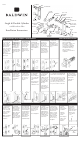
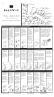
Replacement Part List
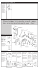

6. Using a 3/32”
drill bit, drill the
mounting holes 3/4”
deep at the locations
previously marked in
Step 1.
5. Prior to drilling
the 3/32” holes,
align knob/lever
hole on inside
plate with lower
2-1/8” face bore and
temporarily place
over the template.
Ensure the correct
hole locations were
marked in Step 1.
2. Position the reinforcing strike and
mark locations for reinforcing screws.
Drill (2) 5/32” pilot holes for 3” long
screws and (2) 1/8” pilot holes for #8
x 3/4” long screws. Mark drill points
5/16” above and below centering
point. Bore (2) 1” dia. holes x 1-1/4”
deep. Chisel out holes for dust box.
1. Using the strike
portion of the mark-
ing template, locate
and mark strike
mounting screws
and centering points
for your door thick-
ness.
3. At the screw
marks, drill (2) 1/8”
dia. pilot holes for
the screws. Bore
7/8” dia. X 3/4”
deep hole.
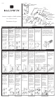
Single & Double Cylinder
with Escutcheon Plate
Installation Instructions
1. Fold template
on scored line and
locate, using the
bottom 2-1/8” bore,
at desired height
(about 40” from
floor). Place folded
edge on low side of
door bevel. Mark
hole locations on
the door for
appropriate backset
& plate style.
2. Caution: Re-
check bore hole
locations before
drilling. Drill the
2-1/8” Face Bores
through the door
first. Drill the 1”
diameter Edge Bores
through to the inside
of the 2-1/8” Face
Bore.
3. Insert the latch
& deadbolt into the
edge of the door.
Trace an outline of
the faceplate onto
the door edge.
Mark screw hole
center locations
and drill 1/8” pilot
holes.
4. Remove latch
& deadbolt and
chisel out both areas
marked in Step 3 to
a depth of 5/32” or
until the faceplates
are flush with door
edge.
4. Chisel out the
area marked in
step 2 to a depth of
1/16” or until strike
is flush with door
frame.
Install strike using
(2) #8 Flat Head
combination screws.
3. Chisel out area
7/32” deep or until all
strikes are flush with
the door frame.
Install strike as
illustrated.
CYLINDER
RING
OUTSIDE PLATE
DUSTBOX
STRIKE
#8 X 3/4”
SCREWS
DEADBOLT
OUTSIDE
ADAPTOR
INSERT
INSIDE PLATE
#8 x 3/4” OVAL
HEAD SCREWS
TURN KNOB
RETAINER
FACE
PLATE
BACKPLATE
#10 X 1-7/8”
CYLINDER
SCREWS
RETAINING CLIP
WAVE WASHER
KNOB
SET SCREW
SPINDLE
#8 X 1-1/4”
FLAT HEAD
SCREWS
INSIDE
ADAPTOR
ALIGNMENT
BUSHINGS
#10 X 3”
WOOD SCREWS
REINFORCING
STRIKE
STRIKE
ALLEN
WRENCH
LATCH
2. Align the strike
and trace outline
onto the door frame
using mounting
screw marks for
location.
1. Close door and
extend deadbolt
several times.
Deadbolt center will
leave mark on door
frame. If mark is not
present, rub chalk
on deadbolt center
and repeat.
Position strike on
center mark. Trace
outside of strike and
mounting holes.
1. Slide the latch
& deadbolt into
the door as shown.
Secure with (2) #8
x 3/4” combination
screws per each
component.
Make sure deadbolt
is thrown prior to
installation.
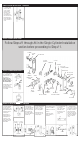
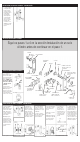
3.Insert the spindle
into the latch with
the ends protruding
from both adaptors.
Slide the alignment
bushings onto the
spindle ends and
into the adaptors.
Tighten the screws
and remove the
alignment bushings.
4. Place the outside
rose onto the adap-
tor and thread on
retainer using the
spanner tool.
Do not fully tighten.
2. Install both
adaptors onto door
and insert (2) #8 x
1-1/4” Flat Head
Screws into inside
adaptor. The inside
adaptor will have
thru-holes and
countersinks for the
screws. Do not fully
tighten at this time.
5. Insert the
cylinder into outside
ring. Slide the cyl-
inder tailpiece into
deadbolt and place
cylinder & ring into
outside plate. Place
backplate against
door & secure with
(2) #10 screws.
6. Place interior
plate subassembly
onto door, inserting
the cylinder tailpiece
into back of the
turnpiece. Thread
retainer onto adap-
tor. Do not fully
tighten. Install #8
oval head screws
into door, Do not
fully tighten.
1” DIA.
EDGE
BORE
2-1/8”
FACE
BORE
7/8”
EDGE BORE
1/8” PILOT HOLES
FOR #8 SCREWS
DRILL 1/8” DIA.
PILOT HOLES FOR
#8 SCREWS.
BORE 1” DIA. HOLE
ABOVE AND BELOW
CENTERING POINT.
5/16” ABOVE
CENTER POINT
CENTER LINE
5/16” BELOW
CENTER POINT
DRILL 5/32” DIA.
PILOT HOLES
FOR 3” SCREWS.
NOTE: LUBRICANT
RECOMMENDED
WHEN INSTALLING
3” REINFORCING
SCREWS.
#8 X 1-1/4”
SCREWS
ALIGNMENT
BUSHINGS
SPINDLE
SPANNER
TOOL
RETAINER
RING
CYLINDER
BACKPLATE
7. Rotate
turnpiece to
check operation
of deadbolt.
Tighten all
screws and
retainers.
Rotate turnpiece
again to check
operation of
deadbolt.
TURNPIECE
STRIKE PREPARATION – LATCH STRIKE PREPARATION – DEADBOLT
SINGLE CYLINDER INSTALLATION
The deadbolt supplied with this
unit has an adjustable
backset feature. It will be set at
2-3/8” backset. To adjust
to 2-3/4” backset, grasp body
and twist faceplate/bolthead
assembly 180° until it stops.
Unit is now ready for
installation in a 2-3/4” backset
configuration.
DOOR PREPARATION: LATCH, DEADBOLT & MOUNTING HOLES ADJUSTING DEADBOLT BACKSET
8. Insert the
spindle into a
knob or lever.
Align scribed mark
with correct door
thickness and
secure with set
screw.
1-3/4”
SET SCREW
SPINDLE
3/32”
MOUNTING
HOLES
THRU-HOLES
KNOB/
LEVER
HOLE
WOOD SCREWS
PK.2018