
Double Cylinder Handleset Installation Guide

Double Cylinder Handleset Installation Instructions
Fits 1-3/4" (44 mm) up to 2" (51 mm) doors
(Thick door service kits for
2" (51 mm) up to 2-1/2" (64 mm) doors
available through customer service)
1-3/4"
(44 mm)
2"
(51 mm)
2-1/4"
(57 mm)
2-1/2"
(64 mm)
Centerline
Ligne médiane
Linea central
2-3/8" 60mm
2-3/4" 70mm
2-3/8" 60mm
2-3/4" 70mm
1-3/4"
(44 mm)
2"
(51 mm)
2-1/4"
(57 mm)
2-1/2"
(64 mm)
Centerline
Ligne médiane
Linea central
Fold
Doble
Plier
Fold
Doble
Plier
5-1/2" 140mm 8-13/32" 214mm
www.baldwinhardware.com • Customer Service 1.800.437.7448
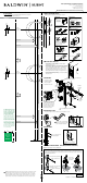
TEMPLATE
Door Preparation
If your door requires drilling, use the supplied template below with the door preparation
instructions available at www.baldwinhardware.com
WARNING: This Manufacturer advises that no lock can provide complete security by itself. This lock
may be defeated by forcible or technical means, or evaded by entry elsewhere on the property.
No lock can substitute for caution, awareness of your environment, and common sense. Builder’s
hardware is available in multiple performance grades to suit the application. In order to enhance
security and reduce risk, you should consult a qualied locksmith or other security professional.
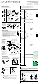
1. Adjust and install latches
Measure your door and prepare using template if needed.
OR
LATCH ASSEMBLY AND INSTALLATION
Handleset Latch
Drive in with hammer.
Snap on collar.
For Square Corner/Round Corner
For Drive-In Latch
If backset of door measures 2 3/4" (70mm),
adjust latch
shown by grasping the spring pin
and moving it to the 2-3/4” slot.
Install with 1/2" (3 mm) screws.
Snap together front and back plate.
Make sure the slant of latch bolt faces
in the direction that the door closes.
Pin
UP
UP
LATCH FACE ASSEMBLY
Remove backplate.
Snap on collar.
For Drive-In Latch
LATCH INSTALLATION
Deadbolt Latch
Install with 1/2" (13 mm) screws.
Drive in with hammer.
For Square Corner/
Round Corner
For Drive-In Latch
OR
Ensure the latch is inserted
with the word “UP” on top.
Note, for a 1-1/2" (38 mm) diameter
hole, test if latch extends and retracts.
Chisel out area if required.
If backset of door
measures 2 3/4"
(70mm), adjust
latch by rotating
face as shown.
Make sure the curve of half round
spindle corresponds to the opening
in the latch; if it does not, reverse the
handing as follows: (1) Pull spindle
away from mechanism, (2) rotate it
1/2 turn (180°) and release.
(2)
(1)
Spindle
2. Measure door thickness
3. Install trim
• If door measures 1-3/4" (44 mm): Use shorter deadbolt
mounting screws in Step 3.
• If door measures between 1-3/4" (44 mm) and 2" (51mm):
Use longer torque blade supplied in the box. See illustrations in
Thick Door Installation Instructions below to replace the torque
blade. After torque blade replacement, proceed to Step 3 and
install deadbolt with longer mounting screws supplied in the box.
• If door is thicker than 2" (51 mm): See Thick Door Installation
Instructions below.
See drilling template for hole location.
Please note: Product
illustrations may differ
from your product.
Installation is the same.
Torque
Blade
deadbolt
interior
cylinder
deadbolt
mounting
screws
chassis
interior
trim
Only use if included in the box. Not used
with SmartKey products.
THICK DOOR KIT INSTALLATION INSTRUCTIONS (AVAILABLE SEPARATELY)
Supports 2" (51 mm) up to 2-1/2" (64 mm) doors
47066 / 02
Copyright © 2011 Baldwin Hardware Corporation
5. Install strike
4. Install knob / lever
Place lever or knob onto chassis and turn set screw clockwise to secure.
The set screws are pre-installed.
They do not need to be removed
prior to knob/lever installation.
Adjust tang as needed.
1/8" (3 mm) pilot holes
may be required.
After the completion of Step 1, replace the existing cylinder torque blade with the longer torque blade
supplied in the kit. Next, replace the handleset spindle mechanism with the one supplied in the kit. Proceed
to Step 3 and install deadbolt interior cylinder and chassis interior trim with longer screws. During Step 5,
install strike supplied in the kit.
Install longer torque blade and
reinstall clip to secure.
Remove clip and torque blade.
Remove and
replace spindle
mechanism
Align pin
Do not distort clip.
Ensure clip ts tightly.
Do not
overtighten
screws.
1"
25mm
1"
25mm
1"
25mm
Measure
after printing.
Mesurer après
imprimer.
Medida después
de la impresión.
The drilling template must be printed
to scale to ensure correct hole
placement. To confirm correct print
scale, the square below must measure
exactly 1" by 1" (25mm x 25mm).
Le gabarit de perçage doit être
imprimé à l’échelle pour assurer le
placement correct des trous. Afin de
confirmer que l’échelle soit correcte,
le carré ci-dessous doit mesurer
exactement 1" x 1" (25mm x 25mm).
La plantilla de perforación deben estar
impresos a escala para confirmar la
correcta colocación de los agujeros.
Con el fin de confirmar que la escala
de impresión es correcta, el cuadrado
de abajo debe medir exactamente
1" x 1" (25mm x 25mm).