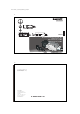
BIS L-405-03_-00_-05-MU_834487_E_0709.p65 1 Manual Electronic Identification Systems BIS Compact Processor BIS L-405-033-00_-05-MU BIS L-405-037-00_-05-MU Deutsch – bitte wenden! 2 No. 834 487 D/E • Edition 0709 Specifications subject to change. Replaces edition 0605. Balluff GmbH Schurwaldstrasse 9 73765 Neuhausen a.d.F. Germany Phone +49 7158 173-0 Fax +49 7158 5010 balluff@balluff.de www.balluff.
BIS L-405-03_-00_-05-MU_834487_E_0709.p65 3 Contents Safety Notes ............................................................................................................................... 4 Introduction BIS L-405 Identification System ........................................................................ 5/6 Application BIS L-405 Processor ......................................................................................... 7-12 CRC data check with BIS L-405-037-... Processor .................
BIS L-405-03_-00_-05-MU_834487_E_0709.p65 5 Introduction BIS L-405 Identification System This manual is intended to guide the user in installing and commissioning the components in the BIS L-405 identification system, so that start-up time is reduced to an absolute minimum. The BIS L-405 identification system belongs to the category of Principle read-only, non-contacting systems.
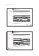
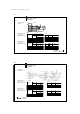
BIS L-405-03_-00_-05-MU_834487_E_0709.p65 7 Application BIS L-405-... Processor Signal description Tag Present (TP): Indicates a data carrier in the field. Address (ADR): Signal change outputs the next data carrier address. Strobe (STR): This signal acknowledges the data output on the parallel interface. ReStart: Deletes the data memory in the BIS L-405 and sets all data outputs to 0. The data carrier is then read again or, if no data carrier is present, only the data outputs are set to 0.
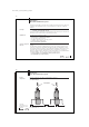
BIS L-405-03_-00_-05-MU_834487_E_0709.p65 9 Application BIS L-405-... Processor Restart when data carrier is present If a ReStart is detected while a data carrier is in the active zone of the read head, the data outputs are switched to 0 and acknowledged with STR. As soon as ReStart goes low again, first the STR signal is inverted as acknowledgement and the data carrier is read out again. From there the process is the same as for a newly detected data carrier.
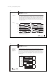
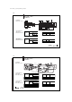
BIS L-405-03_-00_-05-MU_834487_E_0709.p65 11 Application BIS L-405-... Processor Cable test The cable test can be used to check the wiring of the outputs. "ReStart" is switched to "high" and acknowledged with STR. The first data output D0 is not switched until the ADR signal changes. Each time the ADR signal changes the next data output is switched. The STR signal is switched to acknowledge the data output change.
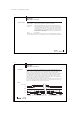
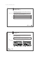
BIS L-405-03_-00_-05-MU_834487_E_0709.p65 13 CRC data check with BIS L-405-037-... Processor The BIS L-405-037-... processor checks for correctness of the data read using a CRC_16 checksum. This CRC_16 checksum is located in Byte 3 and Byte 4 of the data carrier. This ensures especially high data integrity. Initialize data carrier In order to use the CRC_16 procedure, data carriers of type BIS L-10_-05/L must first be initialized using a BIS L-60_ _ processor and the BISCOMRW.exe PC software.
BIS L-405-03_-00_-05-MU_834487_E_0709.p65 15 BIS L-405 Installation Installation BIS L-405 When installing two BIS L-405 on a metal base, there is normally no mutual interference. If a metal frame is located in an unfavorable location, problems may result when reading out the data carriers. In this case the read distance will be reduced to 80 % of the maximum value.
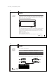
BIS L-405-03_-00_-05-MU_834487_E_0709.p65 17 BIS L-405-...-001-... Installation Clear zone and distances Clear zone 7.3 30 ø100 ø5.3 Power 7.3 TP 6.5 60 46 L 120 Active surface Specifications by data carrier BIS L-405-033-001-... Specifications by data carrier (installed in clear zone) Set screw Speeds: For v = 0 (static condition) Read distance (mm) Speed [m/s] 0-35 0-45 0-15 BIS L-200-03 15 0.4 - BIS L-201-03 20 0.45 - BIS L-202-03 27.5 0.5 BIS L-203-03 10 0.
BIS L-405-03_-00_-05-MU_834487_E_0709.p65 19 BIS L-405-...-003-... Installation Installation BIS L-405-...-003-... Standard length 5 m (max. 20 m) Specifications by data carrier BIS L-405-033-003-... Offset to center axis at distance of: Read (mm) distance (mm) 0-5 0-8 0-11 BIS L-203-03 Specifications by data carrier BIS L-405-037-003-...
BIS L-405-03_-00_-05-MU_834487_E_0709.p65 21 BIS L-405 Installation Lead assignments BIS L-503-...
BIS L-405-03_-00_-05-MU_834487_E_0709.
BIS L-405-03_-00_-05-MU_834487_E_0709.p65 25 BIS L-405 Technical Data General data Housing Plastic (PBT) Temperature range Ambient temperature 0 °C to +60 °C Enclosure rating Enclosure rating IP 67 (only when assembled) Supply voltage Supply voltage Current consumption Output current per output DC 24 V +10 % / –20 % (incl. ripple) ≤ 50 mA with no load max.
BIS L-405-03_-00_-05-MU_834487_E_0709.p65 27 Appendix, ASCII Table DeciControl Hex ASCII mal Code 0 00 Ctrl @ NUL DeciControl Hex ASCII mal Code 22 16 Ctrl V SYN DeciHex ASCII mal 44 2C , DeciHex ASCII mal 65 41 A DeciHex ASCII mal 86 56 V DeciHex ASCII mal 107 6B k 1 01 Ctrl A SOH 23 17 Ctrl W ETB 45 2D - 66 42 B 87 57 W 108 2 02 Ctrl B STX 24 18 Ctrl X CAN 46 2E .