
User's Manual


21
21
english
BIS L-405
Installation
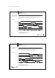
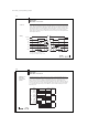
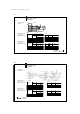
Lead assignments
BIS L-503-...
Connection for Description Color
SUPPLY VOLTAGE
+24 V DC RED
0 V DC BLUE
OUTPUTS
Bit 0 WHITE
Bit 1 BROWN
Bit 2 GREEN
Bit 3 YELLOW
Bit 4 GRAY
Bit 5 ROSE
Bit 6 BLACK
Bit 7 VIOLET
TP WHITE/GREEN
STR BROWN/GREEN
INPUTS
0V WHITE/YELLOW
ReStart GRAY/ROSE
ADR RED/BLUE
SHIELDING SHIELD -
n/c - YELLOW/BROWN
BIS L-405-03_-00_-05-MU_834487_E_0709.p65
22
english22
BIS L-405
Installation
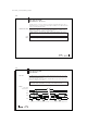
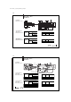
When installing BIS L-405 and BIS L-503, remove the PG fitting. Insert BIS L-503 plug into
the correct sockets of the BIS L-405. Tighten screws and PG fitting.
Remove PG fitting before opening BIS L-405 and BIS L-503.
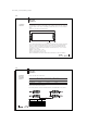
Installing the
BIS L-405 Processor
☞
Active surface Set screw BIS L405 module
BIS L-503 mounting base
Power TP
Set screw
Screws for fastening
mounting base