
User's Manual


23
23
english
BIS L-405
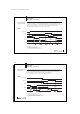
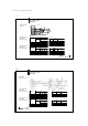
Reorienting and Rotating the Read Head
Reorienting the read
head
- Remove the two screws on the read head base
- Turn the read head module 180°
- Tighten both screws
- Unscrew the set screw
- Read head module can be rotated stepless (complete with read head base) to the
desired position (range: 270°)
- Tighten set screw
- Read head module is secured against over-rotation
Rotating the read
head
Read head modules are not interchangeable!
Active surface
positions
☞
Read head
base
Screw
Active
surface
Set screw
BIS L405 module
BIS L-503
mounting base
Read head
module
BIS L-405-03_-00_-05-MU_834487_E_0709.p65
24
english24
BIS L-405
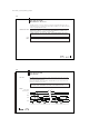
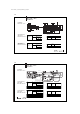
Connection Diagrams
Wiring the inputs
Wiring the outputs
for data
DC+24 V
–
ADR, ReStart
DC+24 V
–
D0...D 7, STR, TP
Load
Opto-
coupler
Supply voltage: DC 24 V +10% / –20% (incl. ripple)
Input high: min. 17 V, typ. 3 mA
Input low: max. 6 V,
< 1.5 mA
Supply voltage: DC 24 V +10% / –20% (incl. ripple)
Output current: max. 50 mA
Voltage drop at 50 mA:
< 1.5 V