
User's Manual

11
11
english
Application
BIS L-405-... Processor
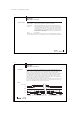
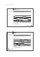
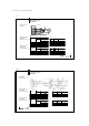
Cable test
The cable test can be used to check the wiring of the outputs. "ReStart" is switched to
"high" and acknowledged with STR. The first data output D0 is not switched until the ADR
signal changes. Each time the ADR signal changes the next data output is switched. The
STR signal is switched to acknowledge the data output change. Once the last data output
D7 has been tested, a change in ADR results in the software version number (2 bytes)
being output. Any further change to ADR does result in a change to the STR signal, but the
data outputs remain at 0.
Timing
ReStart
ADR
D0
D1
D6
D7
STR
t1
t1
t1
t2 t2 t2 t2 t2 t2
t1 = Data output before Strobe ≈ 6 ms
t2 = Response to address change ≤ 15 ms
...
BIS L-405-03_-00_-05-MU_834487_E_0709.p65
12
english12
Application
BIS L-405-... Processor
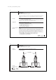
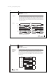
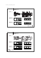
Wiring up to 8
BIS L-405
processors in
parallel
The data lines from up to 8 BIS L-405 processor can be connected in parallel. Since no
data is output until there is a request ("ADR" signal), there is no signal collision among the
processors. It is imperative that you communicate with only one of these processors and
that the output protocol is completely finished before beginning communication with
another processor. If the data lines are wired in parallel, be sure that the data lines have at
least a 10 mA load. If necessary, install appropriate load resistors. If this recommendation
is not followed, the signal change on the data lines can be falsified, resulting in incorrect
data being sent.
D0..D7
ADR1
STR1
TP1
ReStart1
ADR2
STR2 D0..D7
TP2
ReStart2
ADR8
STR8
TP8
ReStart8 D0..D7
D0...D7
R0..R7
I=10mA
Head 1
Head 2
8
2
BIS L-405
BIS L-405
BIS L-405
1
Head 8